
Wheel spacing is an important part of any ground-up bike building project.It also must be addressed when customizing an existing bike.With the vast selection of frames and wheels available today, there is noway any manufacturer can fit every different wheel combo to their frame andprovide exact fitting wheel spacers.
Some frame manufacturers provide a wheel spacer for the left side of thewheel, most of the time this spacer is longer than needed and the exactlength is left up to the bike builder to decide and cut to length. The mostcommon reason that the frame builder only provides the left side spacer is,because the rear caliper mount doubles as the right-side wheel spacer.Again, there are a number of different width caliper mounts, mainlydepending on the style of caliper you choose.
Another factor is especially true of the new crop of wide frames designed tofit the wide tires. Some frame builders widen or offset only theleft side of the frame for belt clearance. Mix in the different width ofcustom wheel hubs and the need for drivetrain offset. The next thing you knowyou are in wheel spacer hell.
Generally motorcycle wheels should track one directly in line with the other. That’s why motorcycles are called, in some circles, asingle-track vehicle; however, this is not always the case. Harley-Davidsonoffsets the rear wheel on some of their Softail models as much as a halfinch to the left, to move the center of gravity back towards the center ofthe motorcycle. As of this writing we know of three different offsets forthe Softails. The different offsets can be found in your service manual inthe chassis section, titled vehicle alignment (page 2-30 in the H-D servicemanual for 1997-1998 Softail models, H-D part number 99482-98). Be sure tocheck the correct service manual for your particular model.
If building a ground-up bike based on a Softail-styled chassis, then buy aservice manual that closely relates to what you’re constructing. Anotherpoint to keep in mind while your fitting a rear wheel to a new frame is, thelocation of the fender mounts. (If you’re building a rigid, it is simplefitting fender struts or a sissy bar to the frame to support the rearfender. Just center the wheel and go. Remember to build fender mounts that clear the disc rotor and the drive pulley or sprocket. Also make sure the tire can be moved for belt adjustment.)
On Softail-style frames, the fender mounts are usually drilled and tappedholes at the top of the frame, just under where the seat will sit. When wefit a wheel to a frame, we like to check first where the fender struts orrails will locate in relation to the wheel and tire combo.Sometimes offsetting the wheel is necessary to be centered in the fender and so you won’t have to carve up a set of custom fender rails. Again, this all depends on the way theframe was designed and built. By placing the wheel in the center of the fender rails you’ll be able to see if the frame is offset or not. If once it’s in the center of the frame rails, it’s not in the center of the swingarm, then it’s offset. Keep it in the center of the frame rails.
The above description may sound confusing and complex, but it really isn’t.With the aid of some photos and the loan of a frame, wheel and tire at MikePowers Customs in Burbank, CA, we can show an easy way to set-up, measure,and make new rear-wheel spacers to get you up and rolling.
The following procedure can be applied to almost any style of bike. One last note… ideally, wheel spacers should be square, meaning that each end of the spacer should be parallel. The optimum tool for making wheel spacers is a lathe; however, some patience with a hacksaw and file or grinder will get the job done.
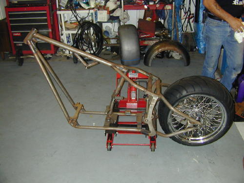
01: At Mike Powers Customs in beautiful Burbank, CA we worked with a newground-up project bike. The frame is a Diamond 250series, Softail style chopper with six inches out and six inches up. Therear wheel is a Superior with a custom, wide hub laced to a 9-inch wide18-inch diameter rim. The tire is 250-40X18 Avon Venom.
02: First thing is to place the frame somewhere solid. Mike uses ascissors lift with the frame strapped to the lift. Now slide the axlethrough the swing arm and wheel. Push or pull the axle all the way forwardor back to insure the axle is parallel to the swing arm pivot shaft andperpendicular to the frame centerline.
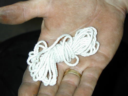
03: To find the centerline of the frame, we used a piece of stringabout ten feet long.
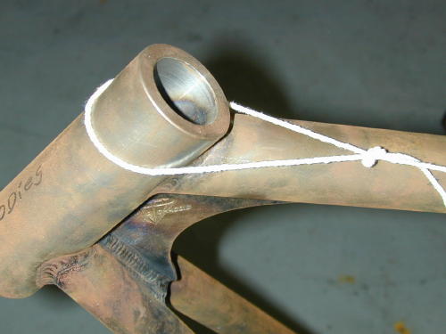
04: A simple loop tied in one end of the string and looped over theframes neck-leave some slack in the loop.
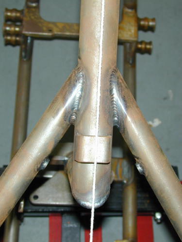
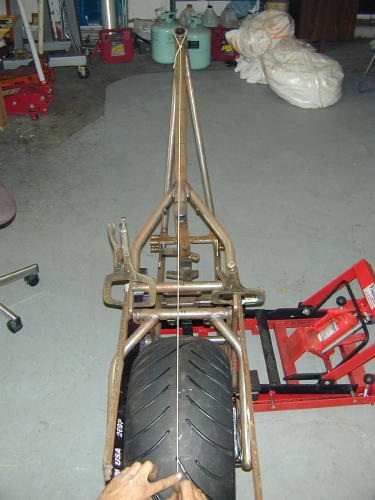
05: Standing behind the wheel, pull the string tight and line it upover the center of the top frame tube.
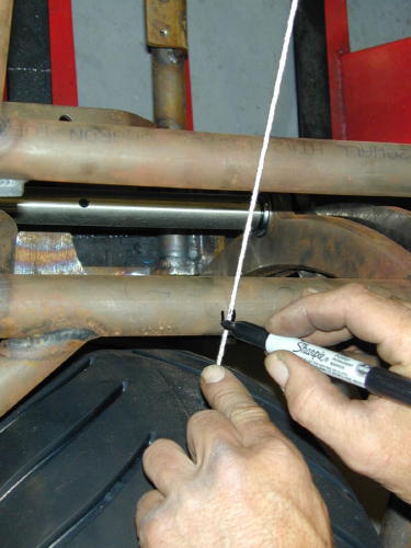
06: Mark the centerline of the frame on the frame and the swingarmwith a Sharpie (marker) to make future sightings easier.
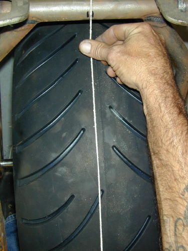
07: Measure the width of the tire and find the center of the tread.Do not rely on the seam of the tire, where the mold line is located. Measure to find the center and mark it.
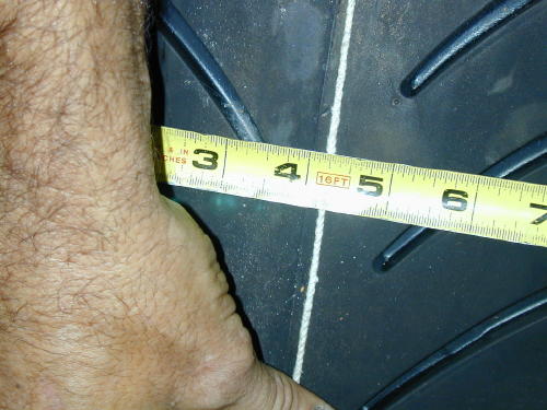
08: The center of our tire is about a quarter-inch from the moldseparation line.
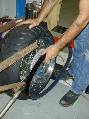
09: Mike slipped the rear drive belt over the pulley, aftermounting the rear pulley on the wheel hub. Once the wheel is located a lookdown the edge of the pulley will tell you if the pulley will needoffsetting.
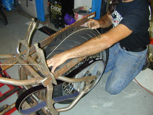
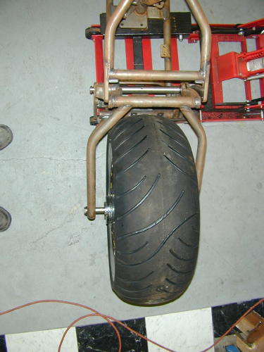
10: Mike clamped two strips of metal to the fender rail mountsto simulate the fender rails. Now pull the string taut and align with yourcenterline marks and center the tire on the string.
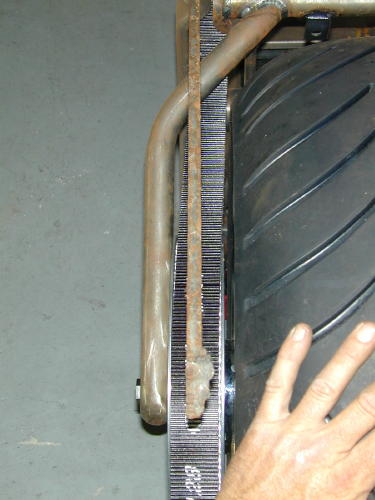
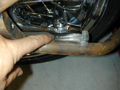
11: With the tire centered on the frame centerline, check andmeasure the distance from the simulated fender struts to the edge of thetire. Also check the distance from the lower swing arm tubes to the tire,remembering that the tire will grow a little once it is up to operatingtemperature. A good rule of thumb to follow is the thickness of a fingerbetween any frame or swing arm tube and the closest part of the tire. Insure that the tire is in the center of the frame rails primarily.
12: Before you start measuring for the wheel spacers cast aneyeball down both sides of the rear drive belt to see how it lines up withthe swing arm and frame. This will give you an idea if a pulley spacer will be needed, something you will have to address once the wheel spacers aremade and installed.
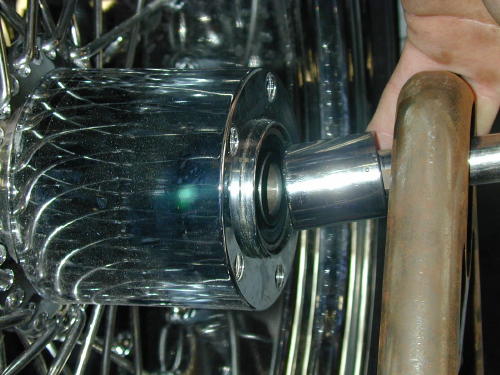
13: When you are satisfied with the location of the wheel inrelation to the frame, swing arm and the fender rails, measure from theinside edge of the frame to the wheel bearing (2000 and later style wheel)or wheel bearing seal spacer and write the figure down.
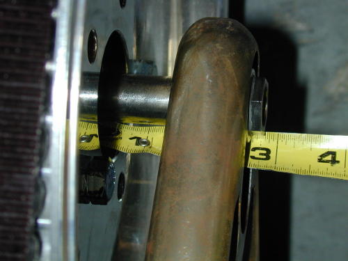
14: On the right side of the wheel move the caliper mount out boardtill it touches the inside of the swing arm, try and do this without movingthe wheel. Now carefully measure the distance between the wheel bearing andthe inside of the caliper mount and write it down. Make sure there is some clearance at the brake stop, even just a 1/16-inch. Make sure the caliper mount is also parallel with the frame.
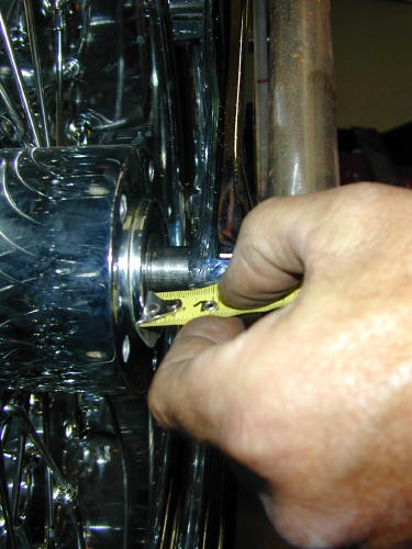
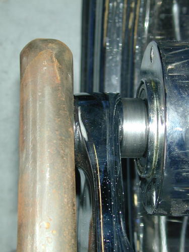
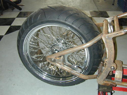
15: This photo shows the relationship of the caliper mount, whereit fits over the anchor mount, welded to the swing arm. Note the minimumamount of overlap of the caliper mount in relation to the anchor. This iswhen the caliper mount is flush against the wheel bearing.
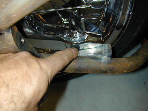
16: With the caliper mount flush against the inside of the swingarm, there is more contact or over lap of the caliper mount with the anchortab.
17: Now is the time to make your new wheel spacers. Once the newspacers are completed, install them on the axle. We ended up with a spacerlength of 1.545 inches on the left. We made our spacers from 1.500 diametersteel with a .750 hole for the axle. We like the larger diameter materialbecause it gives a larger contact area against the swing arm and will notget cocked in the axle slot when you install them.
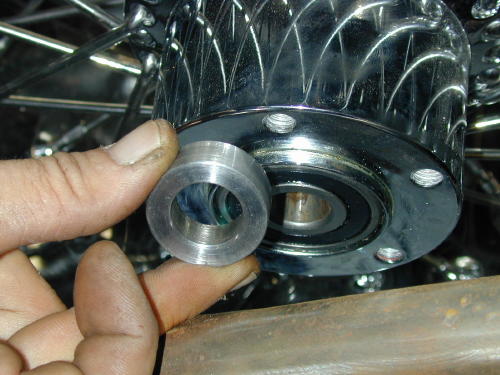
18: On the right side of the wheel, we ended up needing a spacerthat was .630 inches thick again, made from the 1.500 diameter stock.
19: Here is what the right side looks like with the new spacerinstalled. Since we moved the caliper mount .630 inches away from the wheelhub, we’ll have to make a disc rotor spacer the same thickness to properlylocate the disc to the caliper.
20: Here is the finished product. The wheel is where we want it andthe caliper mount has plenty of contact on the anchor mount.
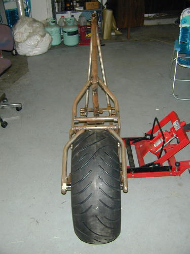
21: The view from the back of the frame looks good. Next we’llcheck out pulley and disc rotor spacers. Remember to measure three times andcut once.
Sources:
Avon Tires
Diamond Frames
Superior Wheels
Mike Powers Customs.
818/5667836