
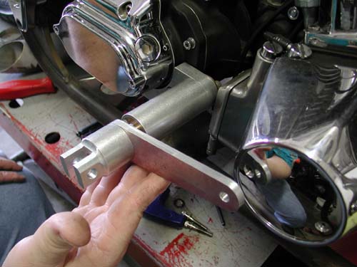
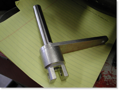
Shrunken FXR mid-controls by Giggie at Compu-Fire. Note: we need flat-headed Allens.
Giggie our master machinist from Compu-Fire rolled up to the Bikernet Headquarters last Saturday. We haven’t seen him for months due in part to his work on new starting systems for the custom market. They are dancing through the final development stages of a system configured to drive off the crank shaft of the motor with a 60- to-one ratio compared to stock 48-to-1. That will leave the area about the tranny available for custom applications or lower seat heights.
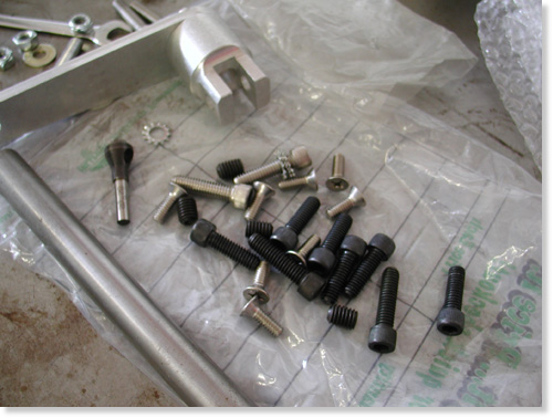
Giggie brought some wrong fasteners but lots of them and counter-sunk drilling tool.
Currently Compu-fire is soon to release a standard starting system, the Gen-2 HT, with 33 percent stronger magnets, 6-roller longer clutch (32 percent longer) with 30 percent more cranking while drawing the same amps from the battery.
Here’s the tranny without the brake pedal components. There’s some tight tolerances going on.
I spoke to him about our cooling debate and here are some of his thoughts. “You want your oil to run at a minimum temp of 205 to eliminate water vapor or condensation that accumulates in oil,” Giggie said. “At 240 to 260 degrees petroleum based oils begin to break down, although synthetic lubricants could be good to 360 degrees. I have my doubts.”
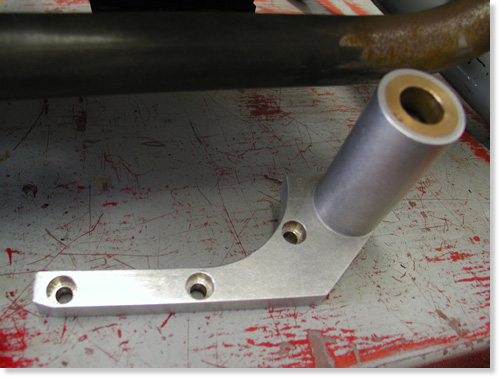
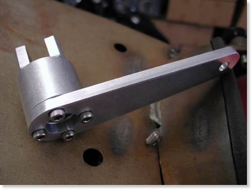
Base bracket to be bolted to the transmission.
Giggie developed an oil cooler for his FLH that kicks on at 220 degrees and off at 200. It has an in-line thermal switch continuously reading oil temp. He installed his cooler in a box with vents and two small electric fans wired to the thermal switch (to cool while idling).
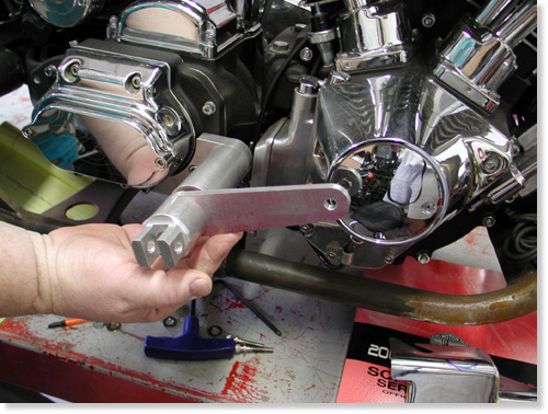
Giggie’s mounting bracket bolted in place.
Regarding our project Giggie dropped off hand machined mid-controls for shifting and rear brakes. Next, we must buy a H-D slave cylinder with remote reservoir with a built in brake switch. We will hide the reservoir behind the oil bag and design a bracket to hold the slave under the trans.
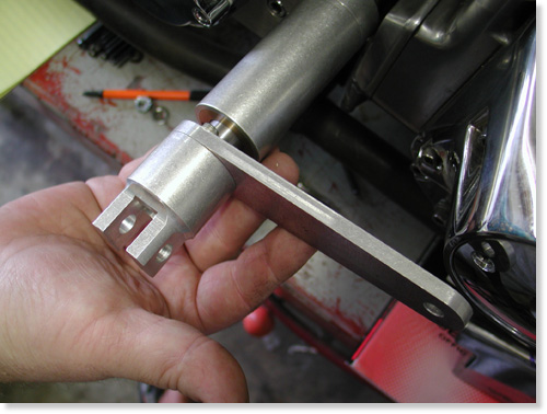
This shows the pedal and shaft in the mounting bracket.
Giggie will supply us with four more bushings to run behind the shift and brake levers, two 1/8-inch thick and two 1/2-inch thick, to allow us variable spacing away from the engine pulley or point cover on the cone.
Giggie will supply two different bushing to be installed between the brake lever and the mounting sleeve. We’ll need the space to clear the point cover.
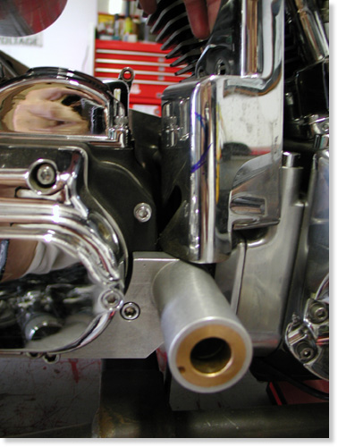
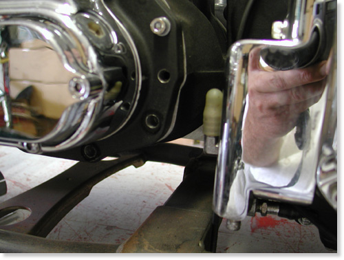
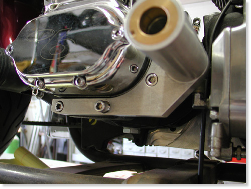
Unfortunately the sleeve hit the oil pump cover. We may be able to remove enough material or just polish the pump. The oil pump inlet fitting will also need to be turned down. It’s close.
With the bushings in hand we can develop our final linkage behind the BDL belt drive plate and Giggie’s tranny plate to connect with the slave piston.
In both cases we need to cut and machine the other end of the shaft, depending on the linkage.
I’ve decided to remanufacture the exhaust system which is now a tight fit around the new brake linkage. Giggie also machined the foot peg mounts to accept any standard, pivoting foot pegs.
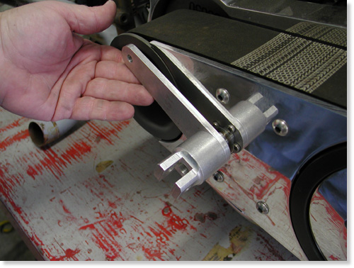
The slick new mid controls for shifting slid through bushings machined into the BDL outter and inner covers.
Next we need the bushings, slave cylinder and a day in the garage hammering and welding a new set of pipes.
–Bandit

Back To Part 10, Page 2