
This thread is an R rated story, and contains new and advanced technology. Those stuck in 1945 should please close this now and move on to other stories.
This story contains explicit material for making massive torque and horsepower, while using exotic new and improved parts.
If you remember reading the recent story about Sorensen Performance's new billet Shovelheads, then you already know who Mike Sorensen is. Mike has been busy again. And the world has changed because of him.
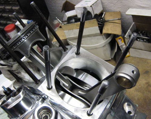
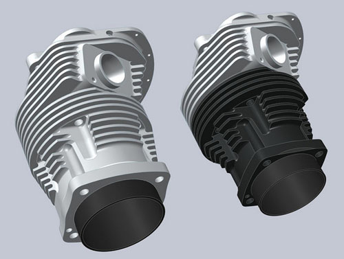
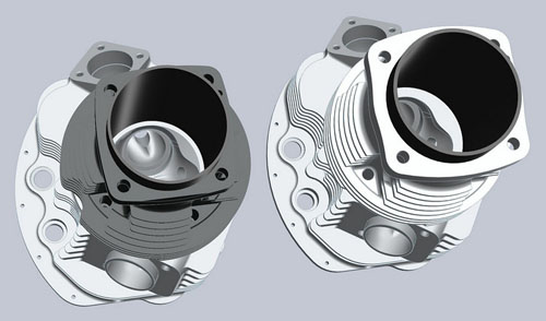
Mike is building the motor we discuss in this story, at his shop in Saskatchewan, Canada. It's based upon an Ultima 127-inch lower end, and all the Sorensen Performance goodies required to melt roads. Follow along as Mike takes us through the build. Oh, and since this fucker needs to breathe Mike had a special set of his new billet heads made up just for it. They are impressive!
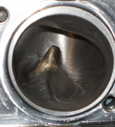
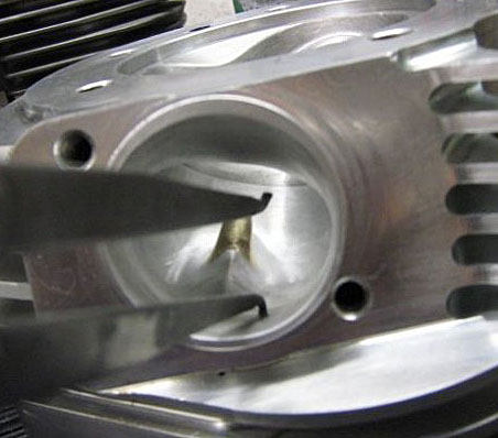
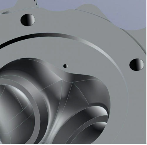
Here is the new port that is being sent for cadding to be integrated into the big bore heads. Flow requirements include 295cfm@650 @28 inches on a 3 5/8-inch barrel. I would be guessing it will flow 300 or better on a 4.250-inch barrel. It has a 1.810 opening with a 1.320 x 1.860 cross section.
That is my goal, 140 plus HP. There should be enough room for a 2.225 valve, depending upon valve to valve clearance. The heads seem to like no more than 88% of the size of the valve then the velocity goes to shit. So, say we have 300cfm now with 2.100. I think 320 or 330 could be a realistic number for airflow. That should put a guy in that 140 HP mark or better. Time will tell, but goal is 140 before the motor leaves the door at 10.1 compression.
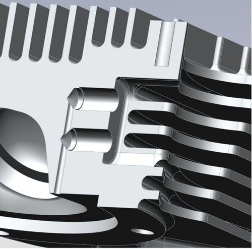
Okay guys, so as we know our Shovels are blessed with less than powerful starters, i.e. shit assed weak starters. The heads will have provision added for dual decompressors, so that starting will not be an issue.
I've been adding everything up and barring some unforeseen cost, it looks like that price for a 127-inch natural is going to be falling in that 9500-9600usd Range turn key, Pre-run on the dyno and tuned before it leaves.
So as long as everything goes smoothly it should be ready for sale Late December/January.
Motor will come with:
* Chrome Rocker boxes
* SP Billet Rockers
* SP Billet Backing plate
* 48MM SuperG carb/thunderjetted (or thunderjets haha)
* Midwest adjustable ignition
* SP Billet Intake
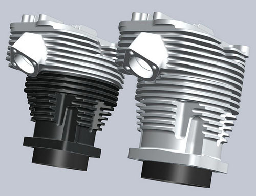
* SP Billet heads
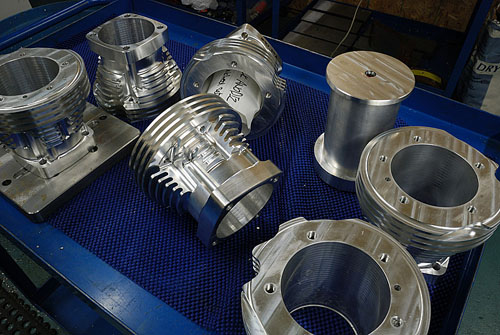
* SP Billet Barrels with internal drains.
* SP Billet Lifter blocks
* Midwest lifters
* Midwest 127″Lowerend (Ultima)
* 325Cfm Bigass aircleaner K&N
Hmmm. MCAdvantage wants 7500usd for a 90hp 107-inch with no carb or ignition, cast hot running barrels with external drains and cast heads (which they don't have) and Shovel valve train.
If anyone is really serious about wanting a 127 drop me an e-mail, so I an idea of what I need to make.
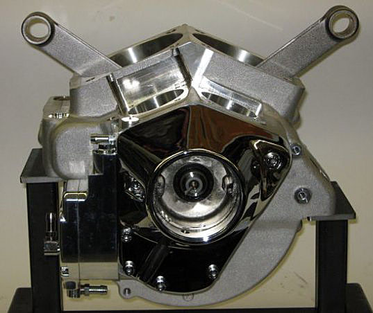
This is the first 127-inch motor being built in front of your Bikernet eyes. The bottom end is a proven combo.
The topend, i.e. heads, intake, rockers have all been proven as tough and problem free on the 93-inch. My 93 has well over 500 pulls on the dyno, still hasn't been ringed and has seen some nitrous as well. All Mike's parts are small runs and not mass produced. Gord and Steve take a lot of pride in their work, as do I. So all SP parts are very well machined.
“I will give a 6-month warranty on the 127-inch motors,” said Mike.
Mike takes a long time to build engines, and so far in 10 years has never been forced to warranty an engine. “I will not warranty stupidity (i.e. over revving and stretching the valves out,” Mike said, “bending pushrods from over revving, nitrous melting the pistons, running it as a drag motor in a drag bike, or snapping a rod.”
If Mike did something wrong, he'll take care of it! Also each motor will be pre run on the dyno and tuned before it even leaves Mike's shop, that way he ensures everything is perfect before it leaves.
The idea is that this motor will be a mirror image of the Ultima 127, 10.1 compression, flattop pistons, medium cam, and terrific throttle response built in. It should produce good mileage (unless you ride WOT all the time, haha). You should be able to get on this and ride anywhere. This is also the reason for the dual decompressors; “I'm trying to make this motor as easy for you guys as possible,” said Mike. “Stuff it in and go.”
If 130-140hp isn't enough, then I can turn it up with domed pistons, hotter cam, and bigger valves.This will be a good idling motor, and pull from basically idle to 5800rpm and be done.
Mike tries to make all his stuff strike the power band from 2200 rpms up. “On the smaller engines, I try to make them so they come on early and just keep building power without falling off, “Mike said, “so, you have great ride-ability.” When you pull the stick back you have power right up to 6000 to 6800, depending how you set up the smaller motors. “That's why I prefer big air and small to medium cams.”
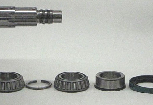


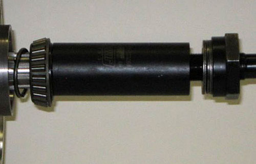
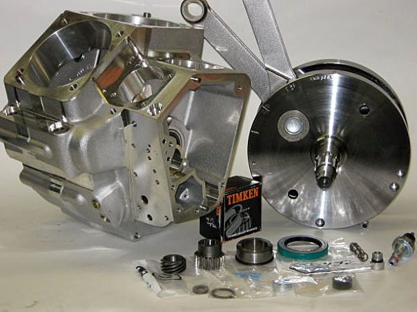
Next, Mike pressed on one Timken bearing tight to the crank using a special JIMS tool. Then he took sanitized cases and set the crank in one half dry, no lube. Then he set the other half on and used three or four bolts to hold the cases tight. Then he slid over the Timken spacer, and then the other bearing set (make sure it's facing the correct direction). He took his fancy JIMS bearing installer tool and set the bearing till it stopped snug.
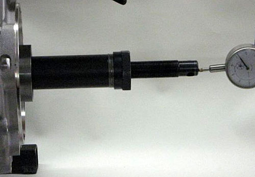
It doesn't matter which end of the crank you measure the end play, just measure it. “I set them .003 to .005,” said Mike. “DO NOT skip this step and for performance use don't go tighter than .003.”
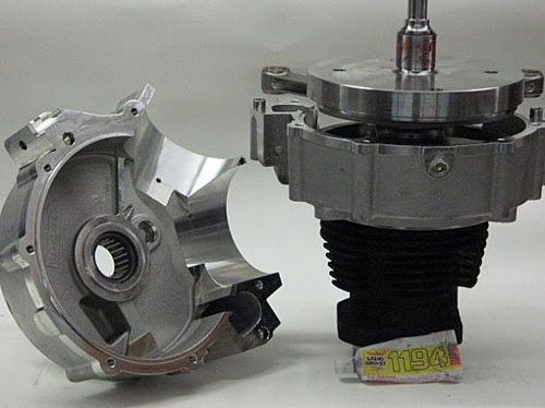
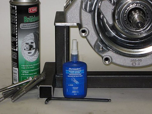
Providing the endplay checked out the first time, we didn't have to press the crank out to change the spacer. “Set the one-half up like I have here and acetone everything clean,” Mike said. “Put a film of 1194 Threebond case sealant on each side of the case. Let it set up for a few minutes then assemble the cases.”
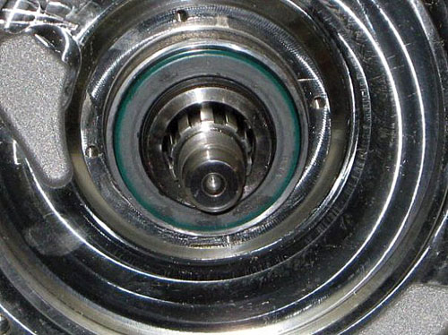
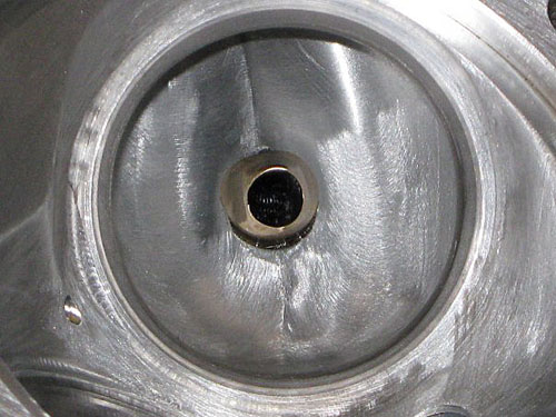
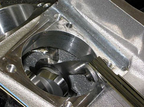
The cases are together and those bearings are dry. Mike tips them on their side and squirts a bunch of oil into the bearings, runs the crank around and adds more oil until it's well lubed. Mike prelubes the front roller bearing in the case before dropping the half on. The 127-inch uses a sturdy roller bearing in the front half instead of a bushing. Tough stuff!
Mike put the spacer in and then installed the seal. Some guys like to run it this way. Some guys like to put it in backwards. Either works, I like this way.
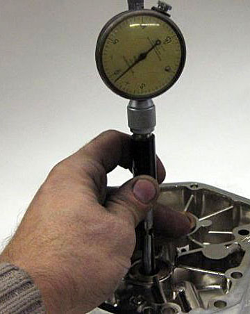
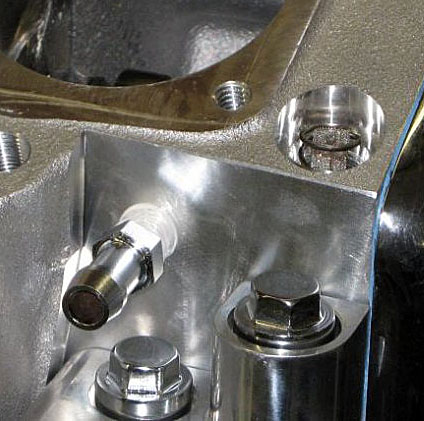
Mike slid the breather in. I like this method of checking actual clearance. Put the cover on with the gasket and torque it down. Remove and cut the putty in half and measure it. This spacer came in at .014.
Time to put the pump in. “Remember to take the whole pump apart wash, inspect and lube it up,” said Mike. This one was full of polishing grit. “I would have had this bolted on but dumb ass sent me a fucking 1984 pump instead of the 1992 and up pump.”
Mike slide the pump in (proper pump this time) and held the drive gear in, while sliding shaft through. He fit that little key in the keyway and then had a gay old time installing that wonderfully easy to install snap ring.
When tightening up the oil pump before you snug it down make sure all the gaskets are fit comfortably. Mike slowly rotated the engine as he snugged the bolts. Rotating helped align everything. If he runs into a binding problem, it needs further investigation.
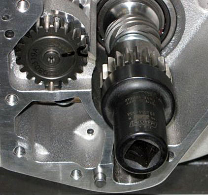
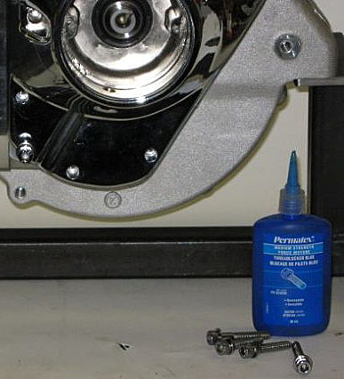
Now, put some red Loctite on the pinion nut, clean with acetone first to remove any oil or grease. Remember it's a left-hand thread. Use your fancy JIMS socket and torque her down.
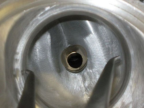
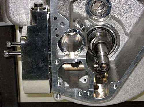
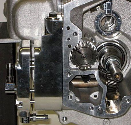
Using a caliper setup with a split ball gauge, Mike measured the cam cover bushing. This cover was so tight it wouldn't even go on. He honed out both the pinion and cam hole to .001 clearance. It was still tight going on. But it'll break in quick. He remembered to lube the pinion and cam before he installed the cover.
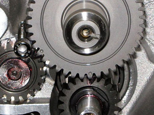
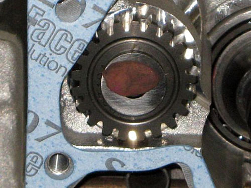
Now stuff you're bumper stick in. This is a Midwest 264, 268 cam. I'll be using my 1.625 rockers. So, it will give me a 620 lift. Mike will offer hotter cams with 650 lift and aggressive lobes in the near future. Line up the dots. I stuck the bolt in for Hawg, as he was mentioned last time, that I should show it lined up.
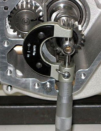
Mike stuck the cover on with gasket and shims and measured the endplay. This one has .011. So, it was time to torque the cover down.
Next time around we start installing that massive top end. Ooh, shiny billet stuff everywhere. I can't fucking wait. Shit, this engine was sold before completion. The new customer requested 12.5:1 compression pistons and the biggest cam Mike has. You'll see the engine come together and face the dyno on Bikernet.
–Rebel