
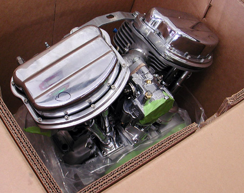
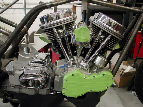
You can imagine how jazzed I was to receive the 120-inch Accurate Engineering Panhead engine from Yellow Freight. I’m a major fan of Panheads. Hell, I was born in ’48, but don’t tell anyone.
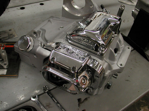
Shortly thereafter the Baker Transmission, 6-speed, touring unit with the oil bag under it, arrived. I also discovered that all my grandiose notions for moving the controls forward might fail. I needed the driveline in place to study the space available.
At first we were going to follow John Reed’s DVD instruction on installing the driveline in his frame, by lowering the frame over the driveline, with both on their sides. We discovered that his notion is killer if the frame is bare, no front end or swingarm.
After removing the bars, dash, fairing, tank and seat, we though we were ready for the Reed installation system. We bolted the system together, tried laying it over and dropping the frame on top, then gave up. We pulled the engine and tranny apart and headed in another direction.
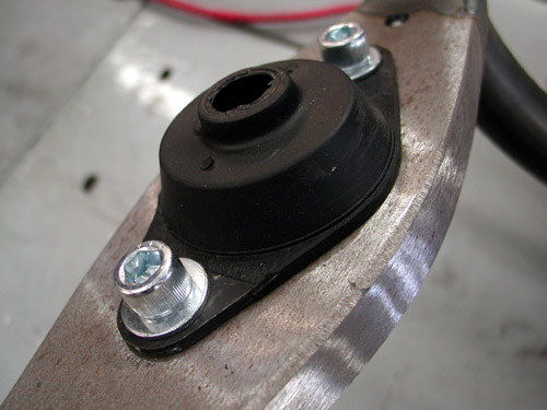
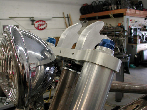
I pulled and began to install the driveline mounting gear including the front mount isolator and the top motormount.
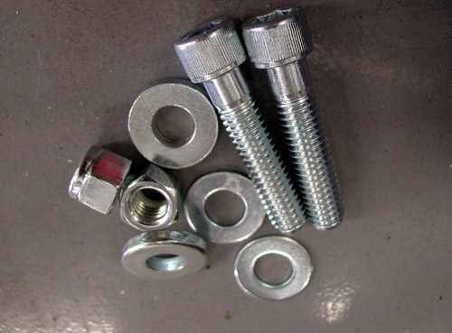
All the fasteners are labeled in bags, although we hope to use stainless Allens or even safety wired stainless in the future.
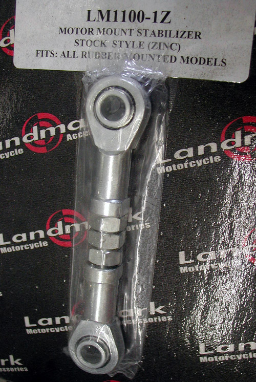
I also pulled the heim joints needed to align the engine and trans. Then I loosened the rear motormounts and tapped the swingarm axle out.

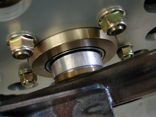
Next I blocked up and padded the transmission, dropping it into the swingarm which by the grace of the Chrome God remained in place.

With all the swingarm axle seals, washers and parts in place we returned the axle, except this time it slipped through the transmission.
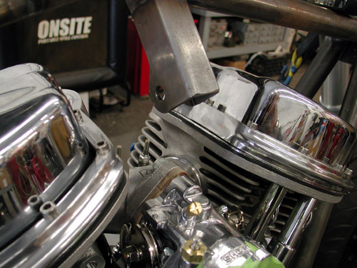
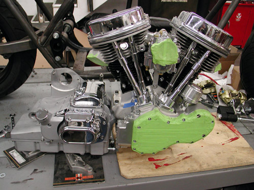
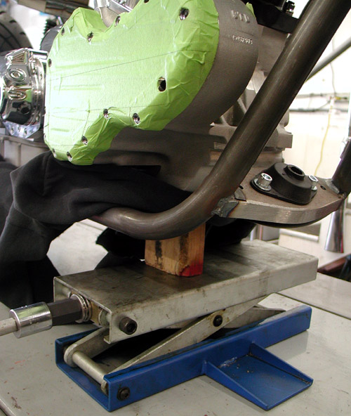
It was time for the engine and I was concerned that I would be forced to remove the carb to clear the top motormount, but that wasn’t the case. The engine slipped right in.
With a jack and wood block under the engine, I aligned it with the tranny, dropped in the bolts and went to work. I always watch out for cross threading into aluminum. If it feels strange, I back ‘em out and shoot for better alignment.
Next, I installed the top motormount and heim joint. Before I messed with the controls, I wanted to make sure the chain and driveline was in perfect alignment.
Here’s an example regarding alignment. I bolted in the engine and tranny. Everything looked cool except the rear sprockets.
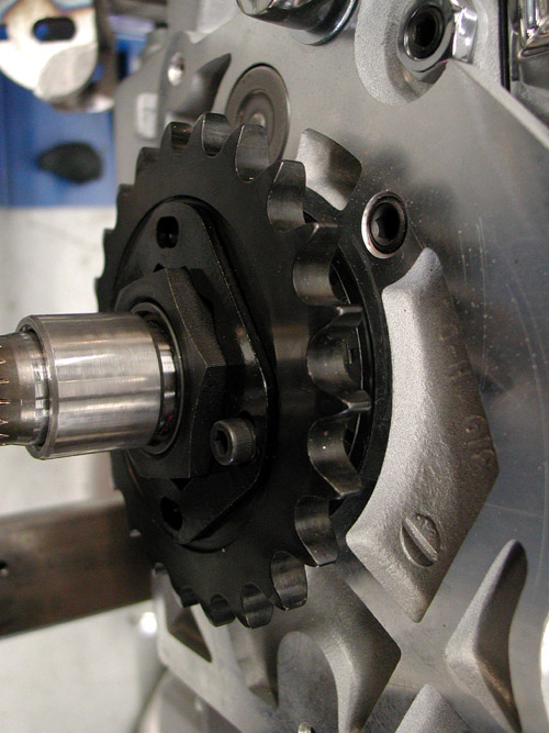
I looked down over the rear sprocket and couldn’t see the tranny sprocket. That made me nervous.
Then I remembered an odd sized aluminum spacer and John Reed’s mechanical drawing. It replaced one of the rear wheel spacers and moved the wheel about 1/8 of an inch to the right. That helped.
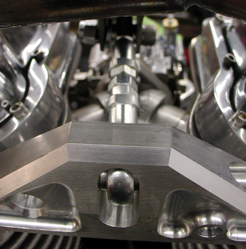
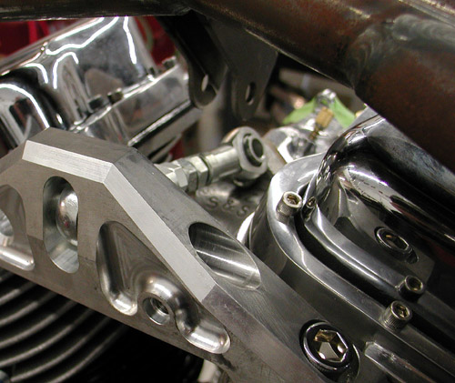
I installed the top heim joint, made sure the frame was level and the engine perpendicular to the lift.
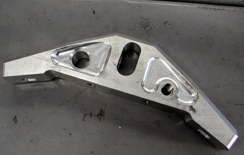
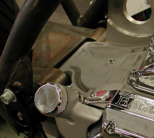
I had to find a bigger bolt for the front motormount plate. I made sure the rear wheel was aligned, then the engine and tranny aligned.
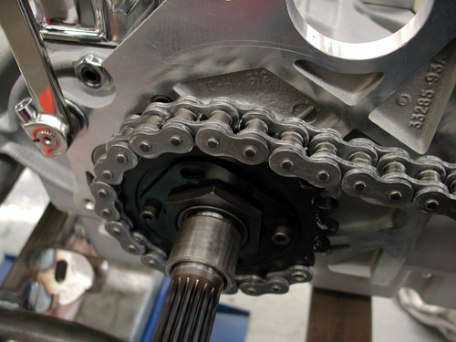
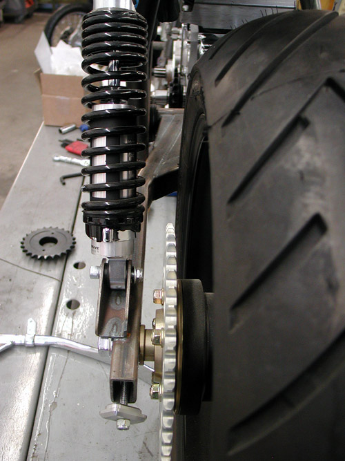
The first time I slipped a Custom Chrome O-ring chain over the sprockets I wasn’t happy. It hit the tire and wasn’t even close to being aligned.
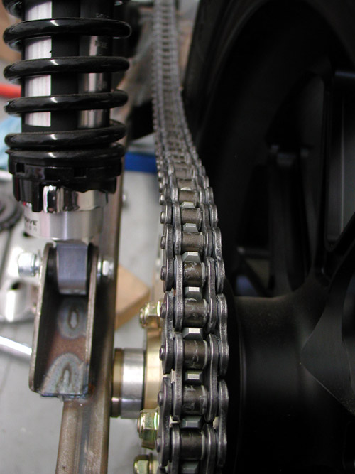
After carefully aligning all the elements the chain jumped into a straight groove from sprocket to sprocket. Next we’ll move onto the foot controls and the rear brake lever. Hang on.


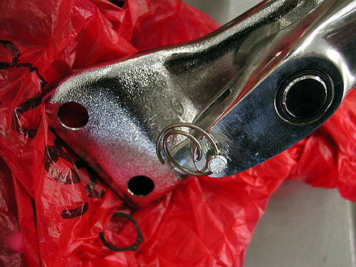
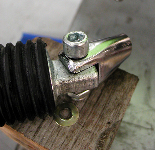
This continued segment will take us through my vague thinking regarding the controls. We initially thought I could move the controls forward and still use the stock aluminum brake lever arm. I even took it apart and modified it to accept the Heim joint on the end of the linkage rod.
We modified it by removing one of the tangs, but discovered that this pedal assembly wouldn’t work at all. Time for plan B, which always works out better.
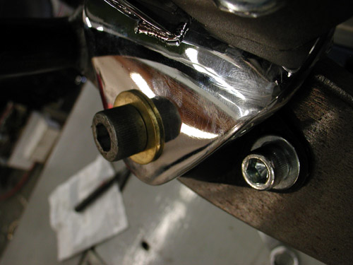
Here’s the heim joint connected to the modified pedal just before we shit-canned the notion.

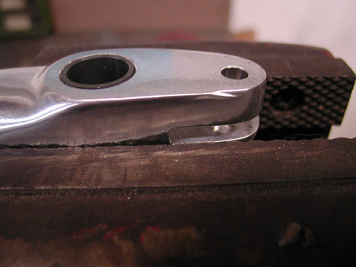
We cut apart the foot peg bracket to lower the peg position. In Part 7 I ran this John Reed quote, but I was premature. It applies here, since this is where we cut the massive cast peg mounts.
“The primaries are fxr/dresser system,” John Reed said. “You can weld the steel footpeg brackets, I am pretty sure they aredrop forgings. I put mine in a mill and machined the shit out of them to make themlighter. But if you are using the bike on the salt,you want to keep as much weight as the motor can pull.”
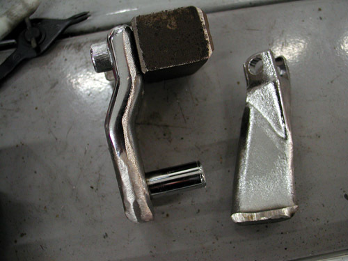
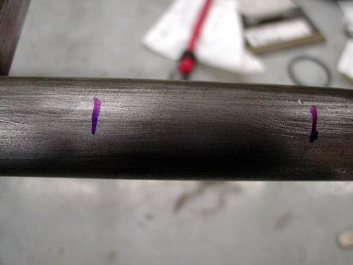
So I did. I cut the forging in two, made a mark on the frame where the bracket could go, checked the spacing and went to work.
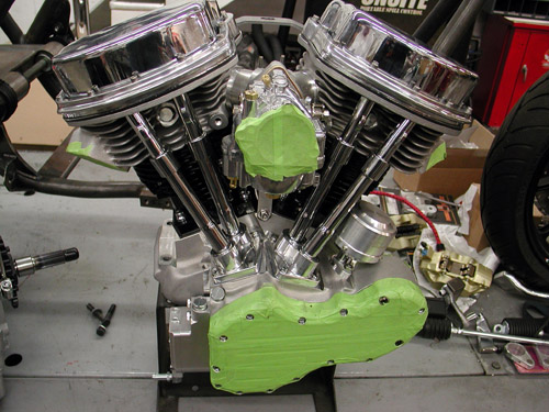
Damn, that’s a sweet looking engine from Accurate Engineering. Mistress Marylin is working for Berry Wardlaw, the prez of Accurate. She’s promised a tech story on all of Berry’s engine secrets. I’m waiting.
Okay, we needed to finish up the controls and the exhaust system before the bike could be torn apart and sent to paint.
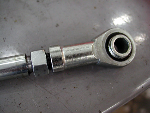
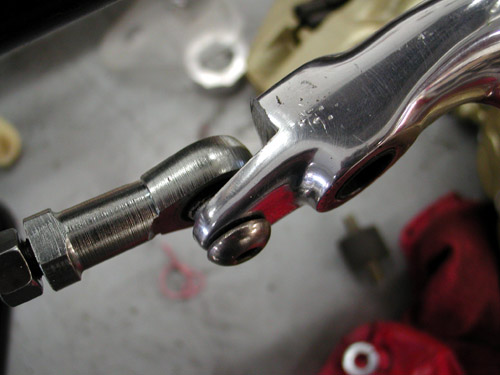
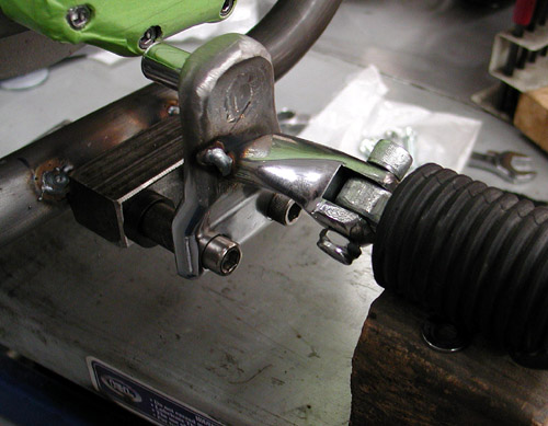
I try to point out my mistakes to prevent you from making the same bullshit errors. See the heim joint on the rod and where it’s positioned. I used it as a guide to confirm where the foot control could go, but I should have set the heim joint in the center of the adjustment for flexibility.
Here’s the chunk with the peg mount. I made sure the peg was positioned, at the angle it was intended, before I tacked it into place. I ground the chrome away from the weld area and fired up the MIG.
With the peg in place I went to work on the control arm. I pressed the tephlon bushings out of the stock aluminum brake arm and went digging around the shop for the exact ID tubing for the lever axle.
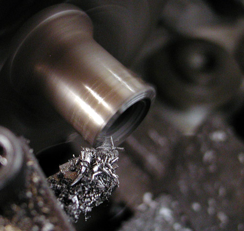
Here’s what I found and chucked it into the Bikernet lathe for some fine tuning. I welded an arm to it out of hot rolled ½-inch round stock, then a spacer on the end and machined a brass treasure.
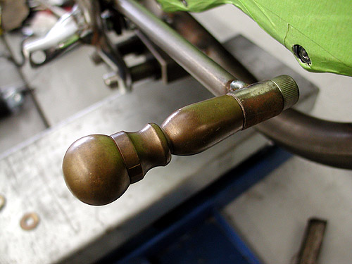
Just down the street is a nautical junk yard. Some guy who works on the docks has salvaged junk boat stuff for decades and he hordes the stuff. Once in a while, reluctantly, he sends a load to an antique swapmeet. I noticed old George loading the truck and bought a couple of porcelain street signs from Beverly Hills. What could be better for our Wilmington Ghetto back yard. George offered me a bonus of brass mementos. I didn’t see much I liked except this brass handle thing, which ultimately made my brake and shift levers. I cut it in half, drilled and tapped 3/8 threads.

Here’s the brake lever in place with the linkage attached. I won’t press in the Tephlon bushings until all the parts are powder coated and ready for final assembly.
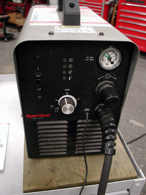
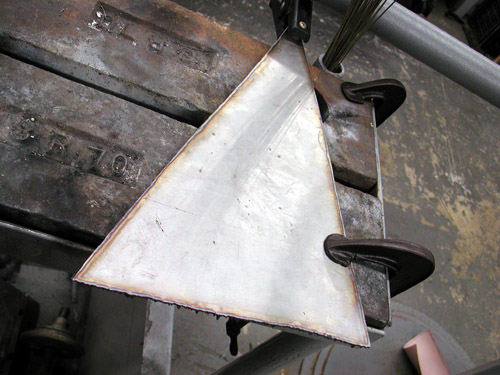
With the handy Plasma Cutter I cut two side panels to afford me number plate space and take up that gap in the frame
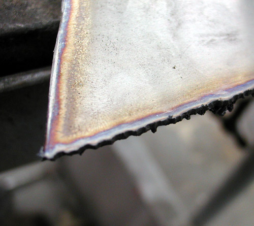
I used the 1/16-inch stainless sheet for this, since it was handy. I could have gone lighter, but at Bonneville, it’s not a factor. This shot gives you a notion of the accuracy of the cut. Lot’s of grinding, sanding and filing brought the cuts in line. We started with a paper pattern as we did for the dash.
I’m sure as I use the Plasma more often, my accuracy will improve. It’s amazing and fast, but the grinding, fitting, and sanding takes awhile and patience.
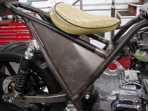
Next, I made tabs in the corners and drilled the sheet for mounting. In the next segment we’ll deal with the panel on the other side of the bike, the shifter peg side and exhaust manufacturing. Then I’ll shift back to the 45. I’ve got some wild historic engine breakdown illustrations demonstrating racing notions, to share.
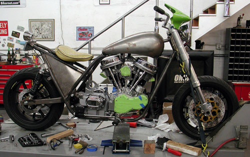
How’s she look?