Continued From Page 1
We beefed up the area for the battery with a block of 2 x 4 wood and placed rubber sheets around it for insulation. The battery fit very loose, so I dug through my scrap drawer for a bicycle inner-tube. I tried wrapping it in coils for the correct thickness. In a sense we were rubber mounting the battery to make it last under the devastating rattle of a rigid. We were also insulating it from the metal walls that surround the battery. (A battery note: If you want to protect your bike and components for the evils of battery acid here’s a notion I’ve used in the past. I find a plastic bleach container, for example. Cut off the bottom of the container and slip it beneath the battery to protect the metal surrounding of the battery and catch any acid escaping the cells.)
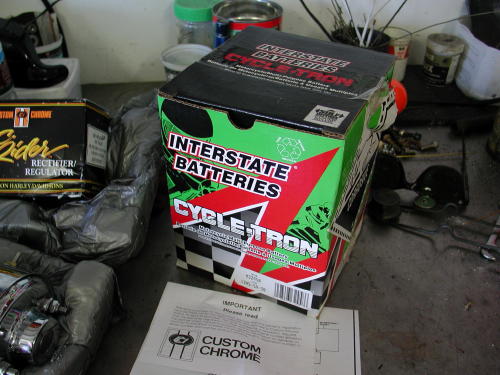
Here’s the new battery, which came with acid. Ready to rock.
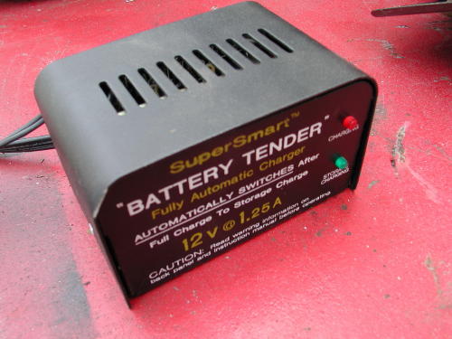
We used the 1.25 amp Battery Tender to charge the battery slowly. The tender monitors progress and shuts off when the battery is fully charged.
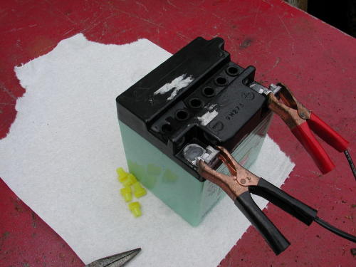
The battery came with battery acid and specific directions for filling each cell. Wrench let the battery set for almost an hour then refilled each cell. Then we charged the battery over night and finally topped off the cells once more before replacing the caps. We kept baking soda and water handy in case we spilled any acid. Extreme care in dealing with this nasty shit, is mandatory.
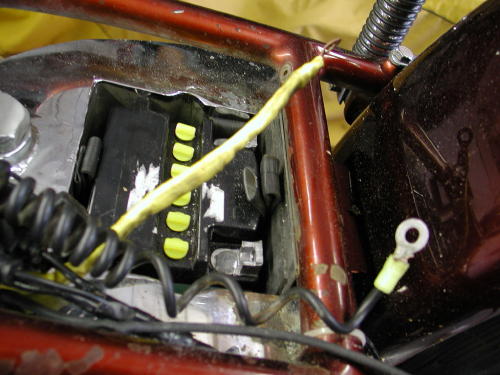
This shows the new battery in place, but wires are not in place. You can see the bicycle inner-tube suspension around the battery.
We could have installed the original metal battery cover but chose not to for a couple of reasons. One, because of the risk of the battery coming in contact with the metal cap (since the cap is not designed for this battery configuration). Two, because of heat and without the cap the battery can breathe. Third, since Sifu had a custom seat, the area was concealed from view and the ugly battery top didn’t show.
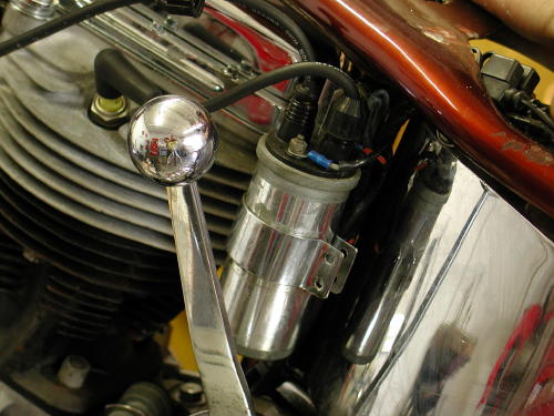
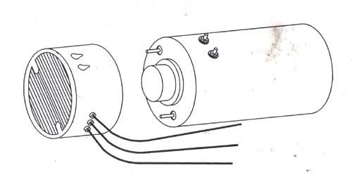
The old coil waiting to be removed.
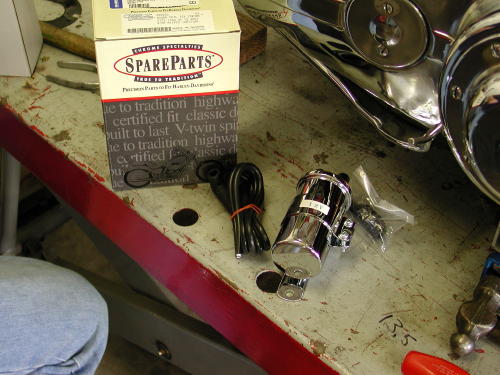
The new Thunder-Bolt coil came with everything including a mounting bracket, fasteners and spark plug wires.
Nuttboy began replacing the coil that comes with everything including the bracket, fasteners, wire lugs and spark plug wires. I generally cut wires or spark plug wires long for safety. Then I trimmed back the insulation and splayed the wires out and over the insulation edge for a guaranteed connection.
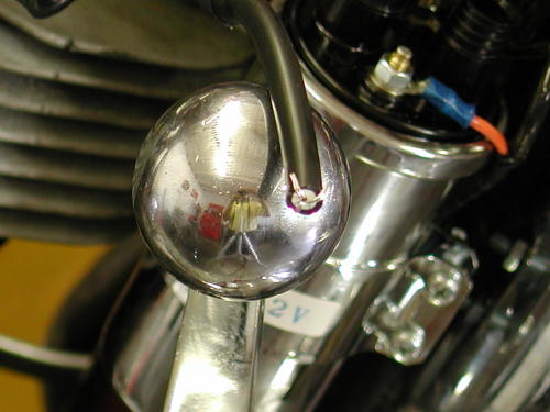
We trim the insulation away from the wires for 1/4-inch and spread the wires out, to insure a connection, even if the wire vibrates around the coil peg.
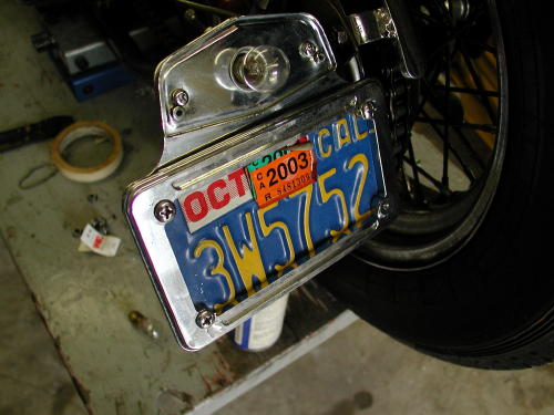
I decided that Sifu’s cracked taillight lens needed to be replaced (it was busted and duck taped in place) and I found a billet license plate ring to conceal the bent and busted edges of the license plate.
About that time Chris Kallas showed up with a ’60s doodle-bug frame that needed pegs and a brake-pedal manufactured. We took a break and became a welding shop for a couple of hours. Believe it or not Kallas is restoring that pieced of shopping-cart crap. He said they’re worth more restored.
Back to the classic Pan. Sifu didn’t have a traditional regulator but a condenser style bolted to the battery. I removed it, traced the wire with a multimeter and used it for the hot connection to the regulator on the end of the generator. Unfortunately, whoever wired this beast, wrapped all the wires in black electrical tape instead of using loom. Some interesting wire configurations was necessary, but it worked out fine. One of the looms of wire had been stuffed between the left engine case and the generator–very hot placement. I moved the wire away from the cases and hid them behind the frame rail.
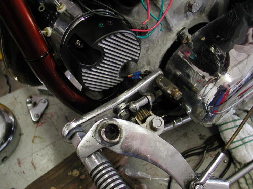
We removed the suicide clutch pedal to install the generator and regulator. Glad we did, we greased the dry pedal shaft.
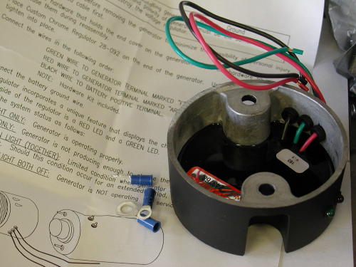
These regulators are terrific and are simple as hell. Just take the cap off your generator and replace it with this unit. Wire the Green wire to the generator terminal marked “F”. Attach the Red wire to the “A” or Armature terminal and the black wire heads back to the hot side of the battery.
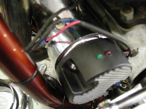
This unit comes with an indicator lighting system to show how it’s working. The red light indicates little or no charge, but when we screwed on the revs, the light turned green demonstrating that the generator is charging. If the lights go out there’s a problem.
With the generator installed with new Custom Chrome Colony hardware, it needed to be polarized. We could only handle this function after the new battery and regulator were wired into the system.
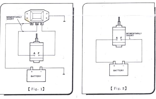
Figure 1, is the diagram for polarizing mechanical regulators. Momentarily connect a jumper wire of adequate gauge (battery cable) between the “Bat” and the “Gen” terminal on the regulator after all wires have been properly connected and before starting the motor.
Fig 2, shows how to polarize a generator system with an electronic regulator or rectifier. Before mounting the generator on the vehicle, place the generator on a non-conducting work surface (like a wooden bench) and connect the positive terminal of a battery to the armature terminal of the generator. Then momentarily “flash” the negative battery terminal to the generator field terminal.
I ordered a Blue Streak set of points and condenser, since I wanted everything to be electrically fresh. We also replaced the sealed beam and the taillight bulb. I set the points at .022 and the plugs at .024. Then I attempted to time the puppy. I pulled the front intake valve clip and the sparkplugs and pushed the bike over until it began to close. Then I took the timing plug out of the left side of the engine and peered in the hole. When the slot arrived I positioned it directly in the rear of the hole pressed against the back of the circle. With an ohm meter Wrench loosened the point plate with a 1/2 inch wrench and rotated the distributor until the points just opened as it was pushed into the advances position. Much care was taken to be exact.
Continued On Page 3