
Digital’s Rigid – Part III
By Bandit |
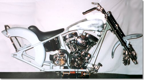
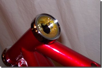
OK, I know….. It’s a shitty photo. Sorry folks. The good news is, it’s promted me to goout and buy a new camera – so keep an eye out for some high quality photography in the nextinstallment.
So here it is. Actually, as I write this, the project is a little further than the photowould indicate, but the time it takes me to get film developed has me at a disadvantage (Did I mention thatcamera will be a digital one?) Whatever the case, at this point, it’s almost completely mockedup.
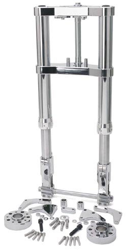
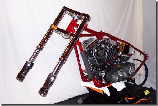
We do have one good photo to show you however (and no, I didn’t take it.) It’s a photoof the front end. I feel it’s one of the centerpieces of the bike. It’s a GCB 54 mm inverted system.It’s massive. They aren’t the most inexpensive forks on the market, but a set offorks this wide will give you the most stable ride you’ve had. Not to mention, they look killer.
This set came from Chrome Specialties. The chromeleg version retails for about $3000, but if you shop around the web, you can sometimes findsomeone with an online shop who will sell them to you for 10-15% less.

These setups come in either a wide or mid-glide style fork, in either satin or chrome. They arestock FL length (30″) which when matched with the rigid frame and 40° rake, provides for anice level stance on the frame.
A couple of things I’ve learned along the way during the mockup.
1.) If you’re building a bike with rake over stock – get prepared to makeuse of internal fork stops. I’ve got somthing kinda jimmy-rigged for the mock up, but willbe putting some in soon.
2.) If you’re making use of a belt drive, be sure you’ve got a tool to remove the race fromthe main shaft. Jim’s makes one. If you go look in their section, you’ll see a “How To” onusing one. I ended up waiting for some period to time to get mine in the mail.
3.) If you think you can use the spacers and the bearings only to determine where yourfront wheel should be placed on the axel – think again. I was able to do this on my last bike,but not on this one. I found that the races in the hub were not quite where I thought theyshould be. They were off about 1/4″ the left as received from the manufacturer when looking at the bike from the front.Since I had a local shop already check the end play on the bearing races, and pack the hubs,I had to make up the difference with spacers….. Which meant I had to order some….. Whichmeant I had to wait another week for parts. Patients is a virtue when building a mail order custom.
4.) Paint. I’ve changed my mind on paint. I’d planned originally to paint the bike orangeand put some racing stripes down the middle. Here’s the problem. I’ll be sending my paintout via UPS to have a friend paint it who lives in California. So, without the chassis, howdo you line up the stripes along the length of the bike? The answer is, you don’t. So muchfor that idea. Instead, here’s a pencil sketch of the artwork that will be adorning the tanks.Jon Towle is working on the final product, and I’m going to see if I can’t sweet talkCrazy Horse into making it a reality in enamel.
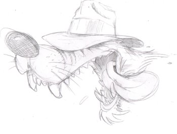
Uncle Big Bad – By Jon Towle
When Jon get’s the artwork done and colored, we’ll have a look to see what color will be best behind it,then it’s time to send the sheetmetal out for paint.
Till next time – Digital
On to Part 4….
Back to Part 2….
Back to the Custom Chrome on Bikernet….
Digital’s Rigid – Part IV
By Bandit |
Sponsored By

Although you haven’t seen it in a fully assembled state, the rigid has actually been mocked up to completion. However, anyone who’s built their own sled knows that an assembled bike without paint and powder just isn’t quite the same as the finished product. Although a primered mock-up will show you the lines and shape of a bike, the machine doesn’t truly come to life until it’s been dawned with color. For that reason, we saved a lot of the assembly detail for you until the paint and powder was complete.
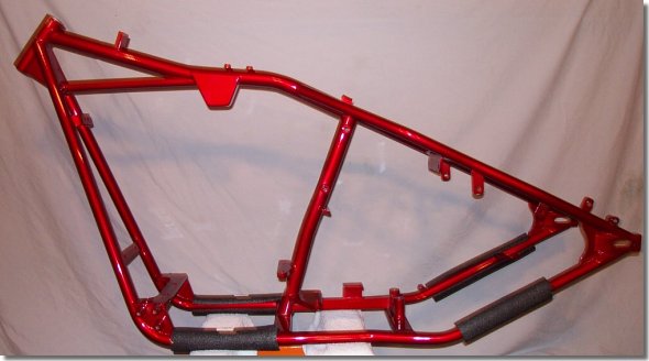
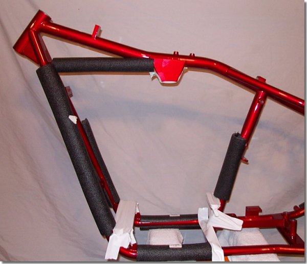
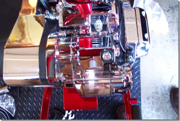
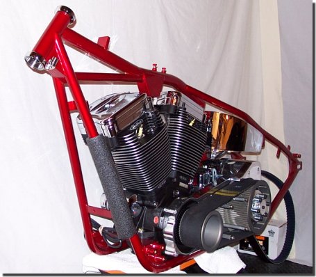
The mocked-up rigid was torn down to the frame, which was sent out for powder coat. It came in only a few days ago and blew my socks off. Although the photos shown here make it look screaming red, it’s actually a deep sunset orange.
The powder coat was done by Hytek Finishes in Kent, Washington. Hytek was the ONLY house I could find in the area that had worked with anything other than a flat powder. This one is a candy orange, color matched to a House of Kolor Kandy paint I’d selected as the base coat for the sheet metal.
Candy paints are valued mostly for their depth. They are made of a base metallic coat covered by a transparent paint. House of Kolor offers a color book for about $42 that you can order from their Web site. Many custom painters around the country use and are familiar with these paints, so they make for a good standard to work with. Candy colors will vary slightly based on the thickness of the transparent color that is used to coat the base.
Candy powder is a little different. The base principle is the same, but you are limited on thickness that can be sprayed because the metal has to be charged to get powder to stick. If the base coat is too thick, you will lose the charge and be unable to get the top coat to stick. Whenever you pick a powder house to do your candy color, make sure they’ve used such paints before because they are tricky to use. This one had a couple of thin spots underneath because the powder coater didn’t want to lay it on too thick. Fortunately, the areas are under the bike that nobody will ever see.
The way I had this matched was to send the House of Kolor sample to Hytek Finishes. They sent the sample to their ‘Prismatic Powder’ supplier, who custom mixed the powder for the job. Not many places do this, so you may have to do some searching. The results are well worth the effort.
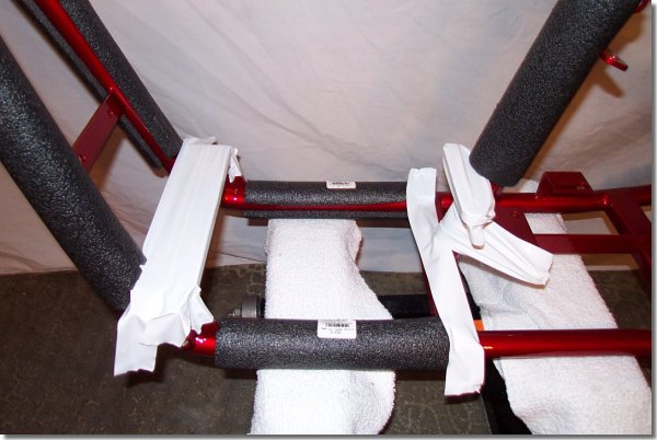
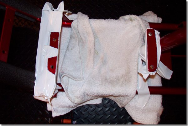
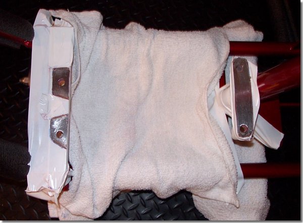
With the frame back in the garage, it was time to get started. The first order of business was to get the power train in place. I started by prepping the area where the engine would sit in the frame. To do this, one must take the time to pad the area so as not to scrape the shit out of the newly finished frame. I used a combination of plastic tape, pipe insulators, towels and bubble wrap to do this.
On to Part 4, Page 2….
Back to Part 3….
Back to Custom Chrome on Bikernet….
Back to Belt Drives Limited on Bikernet….
Digital’s Rigid – Part IV (Continued)
By Bandit |
Sponsored By
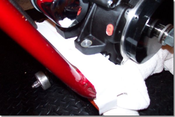
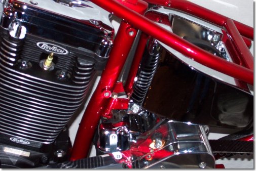
It was then time to put the Revtech engine in place. Caution and ease are the keys to success here. One thing to note: If you build a ride of your own and are using the type of stand I do, which sits under the frame, make sure the rails are around where the bottom of the engine will sit to ensure the motor will fall into place and not sit ON the rails.
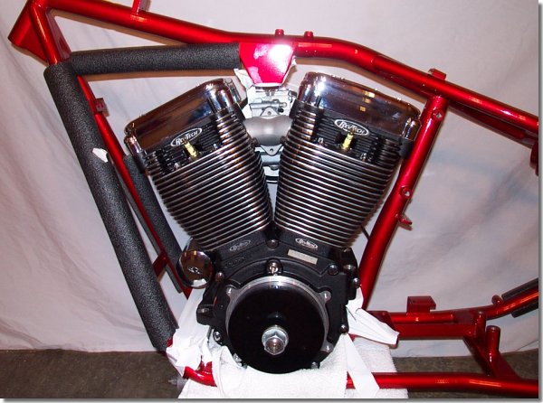
Using a pen, the front and rear engine mounts were traced. The engine was removed and what is left is what you see in the next photo.
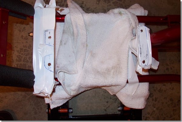
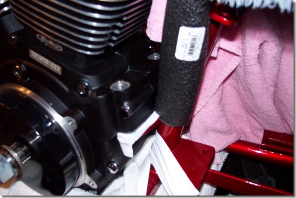
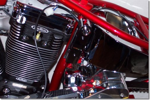
Using a razor blade, I removed the tape from the areas where I planned to mount the engine and prepared to strip the powder coat. The powder must be stripped from the mounting area because the power train must make electrical ground contact to the frame for the ignition, starter and speedo sensor on the transmission.
On to Part 4, Page 3….
Back to Part 4, Page 1….
Back to Custom Chrome on Bikernet….
Back to Belt Drives Limited on Bikernet….
Digital’s Rigid – Part IV (Continued 2)
By Bandit |
Sponsored By
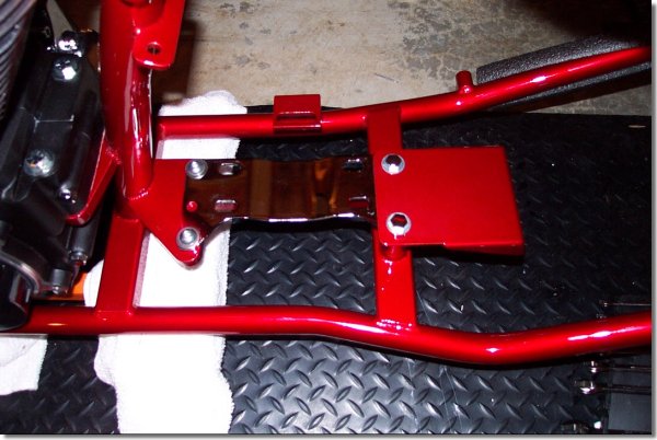
Once the tape was removed, a small Dremel tool was used to strip the area down to the bare metal.
The area was cleaned and the engine was placed back in the frame over the bare metal spots.
On to Part 4, Page 4….
Back to Part 4, Page 2….
Back to Custom Chrome on Bikernet….
Back to Belt Drives Limited on Bikernet….
Digital’s Rigid – Part IV (Continued 3)
By Bandit |
Sponsored By
Once the engine was back in place, the bolts were placed and the tape was removed.
Then it was on to the area where the transmission was to be placed.
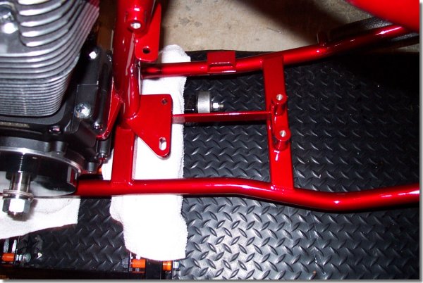
The transmission plate from Custom Chrome and the rear fender mounts were put into place and bolted down.
The transmission was then put in place but not bolted down.
You’ll notice at this point that the secondary pulley is already on the transmission’s output shaft and the shifter lever is in place. Note: You want the shift lever to be straight up and down when bolted in place. The one in the photo required some adjusting to make this correct.
On to Part 4, Page 5….
Back to Part 4, Page 3….
Back to Custom Chrome on Bikernet….
Back to Belt Drives Limited on Bikernet….
Digital’s Rigid – Part IV (Continued 4)
By Bandit |
Sponsored By

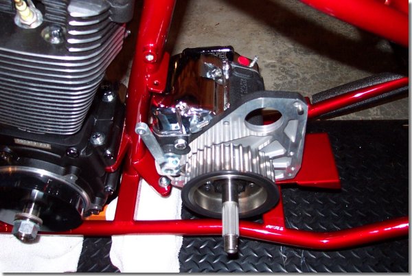
This project uses a BDL open drive system to drive the tranny, so the motor plate was put into place and bolted down while the engine bolts and transmission bolts were still loose. Make sure to use Loctite 242 and to torque the bolts to spec per the instruction sheet provided with the BDL system.
Something to note: This plate comes with its own bearing for the main shaft on the transmission, so the color had to be previously removed from the transmission. A tool from JIMS USA is available for this and can be found here in their section on Bikernet.
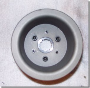
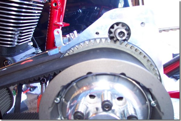
The offset needs to be pinned into the front pulley as shown below.
Both pulleys had to be slid onto the engine and transmission shaft simultaneously.
On to Part 4, Page 6….
Back to Part 4, Page 4….
Back to Custom Chrome on Bikernet….
Back to Belt Drives Limited on Bikernet….
Digital’s Rigid – Part IV (Continued 5)
By Bandit |
Sponsored By
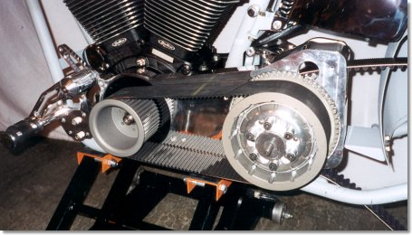
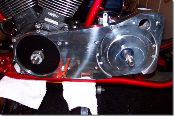
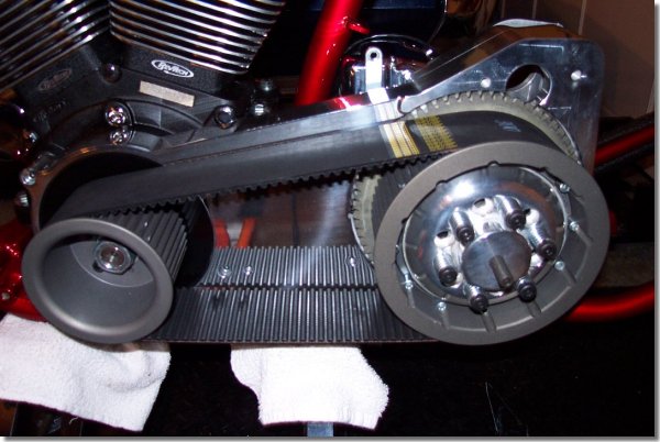
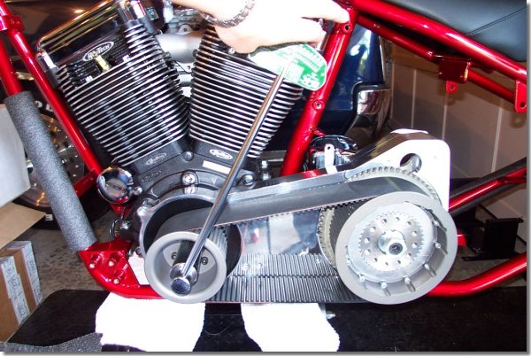
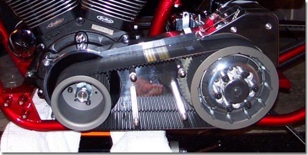
At this point I needed to make sure the front and rear pulleys were even at their outer edges. This was to make sure the belt does not rub on the pulley rim. A long level or other straight edge can be used to do this. If you need to move the front pulley out, Custom Chrome sells some hardened shims just for this purpose that range in thickness from .010 inch to .200 inch thick. Don’t be surprised if you have what you think is a “stock” application and you need shims. Depending on the rotor/stator setup on your motor, you will most likely need to shim the front pulley. Here’s a top view of a system that has been properly aligned.
The spring plate on the clutch had to be removed to allow for bolting the rear pulley to the shaft. This was done by removing the six spring/bolt assemblies and the plate.
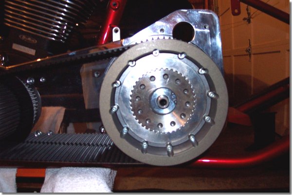
The bolt was torqued down to spec, along with the front pulley. I was then ready to turn the motor to make sure the belt tracked properly. To torque these down, an air compressor and an impact wrench was required. I would never have been able to torque against the motor or transmission using a regular torque wrench unless I had jammed the pulleys.
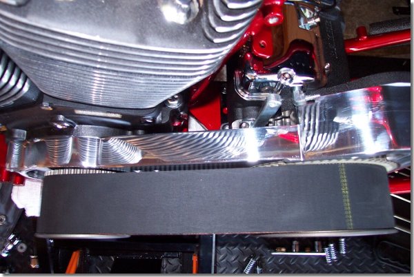
Using a large torque wrench, I turned the motor forward a few times to make sure the belt could make three revolutions and still track to the center of the two pulleys. If you use one of these set ups, it should track as assembled, but if it doesn’t, check the spacing on your front pulley. If you still have problems, you can call BDL and they will walk you through how to shim things up on your frame.
On to Part 4, Page 7….
Back to Part 4, Page 5….
Back to Custom Chrome on Bikernet….
Back to Belt Drives Limited on Bikernet….
Digital’s Rigid – Part IV (Continued 6)
By Bandit |
Sponsored By
Now here’s the test. If you’ve been paying attention, you’ll notice that I DIDN’T put on the secondary belt before we put on the motor plate! Just remember to do this and save yourself the removal of the assembly to fix this mistake.
With everything in place, I put the friction plate back on the secondary pulley and turned the clutch adjusting screw into the plate until it hit the main shaft. I’ll walk through how to adjust this later in the project.

Next, the Spike starter from Custom Chrome into place.
Attached the starter gear…
And bolted the cover on the plate. At this point, I also placed the center cover bolts to hold the cover that will be put on later.
When I was all finished, I torqued the engine and transmission bolts into place. I started by tightening the engine lightly, then the transmission. I then torque the engine to spec, then the transmission. When it was all done, I turned the motor a few more times to make sure the belt still tracked.
Next time, I’ll be installing the front end. – Digital
On to Part 5, Page 1….
Back to Part 4, Page 6….
Back to the Garage….
Back to Custom Chrome on Bikernet….
Back to Belt Drives Limited on Bikernet….
Digital’s Rigid – Part V
By Bandit |
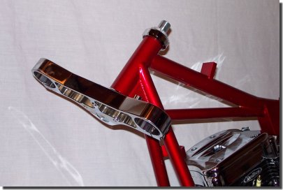
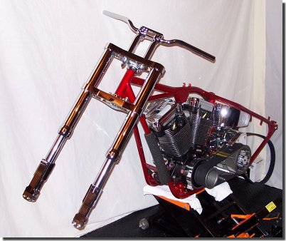
With the help of our friends over at Chrome Specialties, Bandit and I aquired this front end for the project.It’s a set of 54 mm Inverted GBC forks. The 30″ length is just right for this low slung sled.
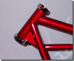
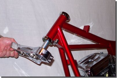
We start by preparing the neck. On this frame, we’ll need neck cups to install the fork.The metal piece below the neck is the custom fork stop that needed to be used.These can be interesting on high-rake frames.Custom Chrome sells a couple of different options that I’ll be looking into later for the project,because I’m not 100% happy with this one.
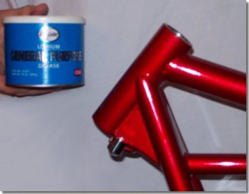
Using fine sand paper, clean the inside of the neck cup to eliminate any rust, powder coat, or paint overspray.Then, coat the inside edges of the neck with some grease to ease the installation.
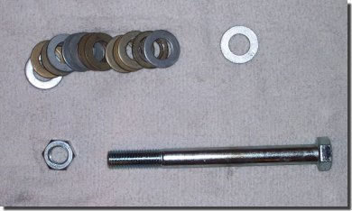
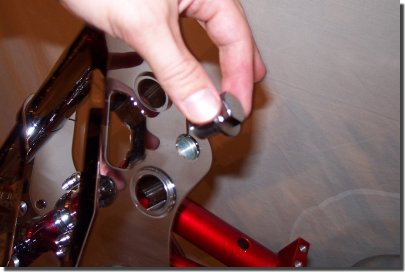
Here are the simple tools used to install the neck cup.A 3/4″ bolt, nut, and washers to make an inexpensive tool that will be used to pull the cups into the neck.
We then took an old rag, cut a couple of small pieces out, and put some small slits in the middle to fit the bolt through.
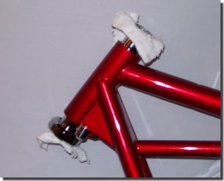
Put a few washers on the bolt, then slip on one of the small rag pieces. Place it through the top cup and set it intoposition at the top of the neck.
Then, slide the lower cup into place, put the second piece of rag on, then the washers and the lower nut. Hand tighten the assembly.Check to make sure the assembly is aligned as to not hit the races with the bolt head and nut. The rags are designed toprotect those races.
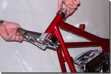
Tighten the whole assembly using a pair of large wrenches – or an impact wrench will make this a lot easier if you have access to air tools. Just make sure everything goes in straight when you tighten the assembly.
Remove the makeshift tool and you’re done.
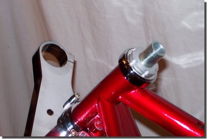
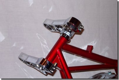
Here’s how the whole thing looks from the front.
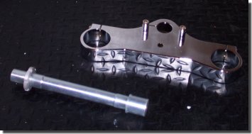
Next, the lower triple clamp needs to be readied for install.
Place the neck shaft into place, and tighten the lower pinch bolts. Place the dust shield on, then the lower bearing. The bearing should then be greased and worked to insure good coverage.
Grease the top cup….
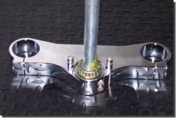
And place the assembly into the neck.
Place the top bearing on the shaft, then…
place the top dust shield and lower – top nut.
The assembly will now stand on it’s own.
Place the top clamp and nut, and tighten lightly. Some play is needed to get the tubes in easily.
At this point, the trees are ready for the tubes.

The tubes need to then be CAREFULLY slid into place. Caution must be taken not to scratch the hell out of the tubes.Some builders actually use wax paper, or other thin barrier to wrap around the tubes during this process. You can alsouse a small screwdriver and padding to spread the pinch clamps a bit, making it easier to slide the tubes into place.
When complete, tighten the pinch bolts around the tubes. Then, tighten the top nut. Close the top pinch assembly around the top bolt LAST.
The front forks are now installed. Simple eh?
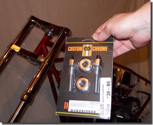
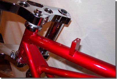
This bolt kit from Custom Chrome needs to be used to mount the risers.
I’ll show you all the bracketry and spacers that are used on the front end later when the wheel assembly is ready.Also – I’m still waiting for sheetmetal and paint, so next time, we’ll do the wiring.
Until then – Digital
On to Part 5, Page 2….
Back to Part 4 Page 7….
Back to Custom Chrome on Bikernet….
Back to Belt Drives Limited on Bikernet….
Digital’s Rigid – Part VI
By Bandit |
Sponsored By
Well, here it is December and I think the painter’s got his nose in the paint can. Suckin’ fumeswill make you goofy. Apparently, it’s made this guy goofy enough to forget I was planning on paying him to do this job.I sent the guy the sheet metal in August. It is still not here. I may have to go shoot the bastard; when he’s done….
At this point, there’s still a few things we can do before the tank and fenders arrive. One of those items is the wiring.
Wiring a bike for most guys probably the single most tedious task of a bike project.To me, it can be somewhat therapeutic. This is a job that requires a lot of patients – so take a few deep breaths before you start.
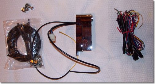
The electrical system of a motorcycle can really be broken down into four distinct sections.Lighting, Instruments, Ignition, and Charging. Most wiring harnesses you see in the Custom Chrome and Chrome Specialtiescatalogs, as well as most others, are built to handle the lighting and DC power distribution. They typically consist ofan electrical box which contains the flashers, breakers, the starter relay, and an L.E.D. panel to help you T-Shoot which circuits are working properly.Many seat-post mounted systems like the one picuted below will also have an integrated key switch as part of the package.Most of these systems will NOT tell you how to completely wire anignition, charging system, or speedo / tach system. It also then goes without saying that the wiring harness will NOTtypically provide all the wire and connectors you will need to wire the ignition, charging system, orinstrument system. For this article, we are going to stick mostly to the lighting portion of thetask, and hit the ignition, charging, and instrument system later.
The backbone of the electrical system on a bike is the wiring harness. I procured this one from Custom Chrome. It’s a seat-postmounting type for use with a single piece tank (with no dash.) It comes complete with instructions,solder connectors, a 30 amp circuit breaker, and an L.E.D. panel which will give you an indicationof which circuits are working and which ones are not.
It mounts on the seat post where most stock Softail’s have a coil system mounted.
The photo below shows the box in place. We had to use a couple of washers behind the boxbecause of an interference with the front oil tank brackets. You can see, the lower bung on theseat post is very close to the oil tank mount.
On to Part 6, Page 2….
Back to Part 5, Page 7….
Back to Chrome Specialties on Bikernet….