I’m going to say, and I might be off base, that most carbs are rebuilt for a couple of reasons: either they sat too long, sucked bad gas, or ran without an air cleaner too long. I would venture to guess that most carbs on custom bikes don’t wear out. I would bet a serious number of carbs are rebuilt because they were sold used, and the new owner wants to be certain it’s in good shape before installing it in a new duty station. We’re going to cover the rebuild process with several recommendations and tips, so hopefully you’ll be able to operate your S&S Super E, G, or Shorty to its fullest extent, enjoying reliable operation for years to come.
Generally carb problems develop from crap in the gas: so always run a fuel filter. Crap in the air; so run and clean your air filter from time to time, as well as crap in the float bowl, from storing the bike too long between start-ups.
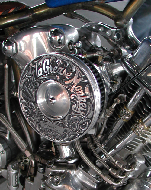
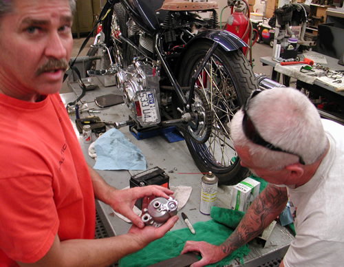
In this case Brad rebuilt his ’61 Panhead and decided to install a used S&S carb, so natch he wanted to inspect it. This process accomplished two strong beneficial elements: maintenance and knowledge. We made the carb new for a long durable high performance life, and now we both know the ins and outs of an S&S carb.
So where do we start? Remove the carb, clean the air cleaner, inspect the fuel filter and replace if necessary. Spray the air cleaner element with an approved element spray based on if you have a foam filter or a paper one. Make sure the intake manifold fits well against the ports and the O-rings are not cracked or damaged, also check the straps to ensure they are cool and secure. Be sure the carb is mounted properly and not held with the manifold clamps or resting against a pushrod tube. That was the case with a professionally built custom bike we worked on recently.

I just glanced at the S&S installation guide, which I will refer to often, and here are a couple of super-basic recommendations: You’re messing with gas, be careful. If you can, handle the operation out in the open. Don’t burn your garage down. Plus, today’s petrol is nasty shit. It will burn your hands. Wait until the bike is cool and disconnect the battery. One spark and your wife will never speak to you again. Make sure you shut off the petcock before you work on your carb. Anytime you’re bike is not running, shut off the petcock.
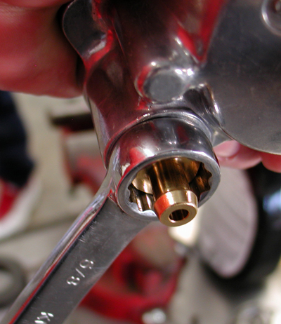
The S&S guide pointed out “Start the installation when you’re fresh.” I like that one. They don’t want you burning your bike and pad to the ground ’cause you ripped off your $500 carb while toking on a bong. It’s a good point. You’re carb is one of a couple of delicate watch mechanisms running your motorcycle. It’s delicate and precise. Take your time with each element, including removing the rubber fuel line from the carb. Often after that little bastard clamp has been snugged against the brass fitting for a couple of years, it’s stuck. Remove the clamp completely. Take a very small sewing machine screwdriver or a pointer and work it under the dried lip of the gas line. Spray some WD40 under the lip and attempt to rotate the screwdriver around the brass nipple base. Let it set for a couple of minutes and it might slip comfortably off.
I’ve seen them so unyielding it would take a come-along to set it free, damage the carb and burn the your mother’s house down in the process. Sometimes it’s best to cut the line with side-cutters above the nipple, remove the carb and deal with it once all the petrol has been eliminated from the carb. Then you can carefully clamp the carb body in a vice and/or slice it off with a sharp knife.
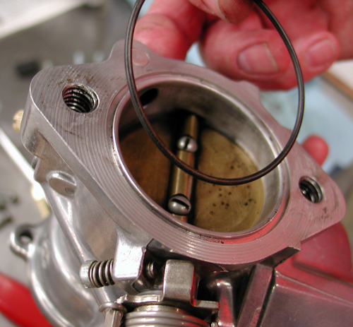
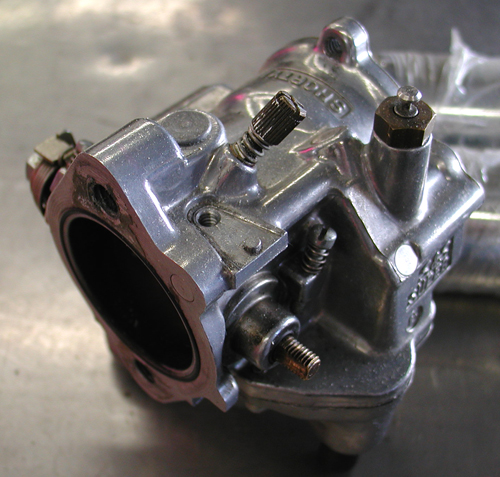
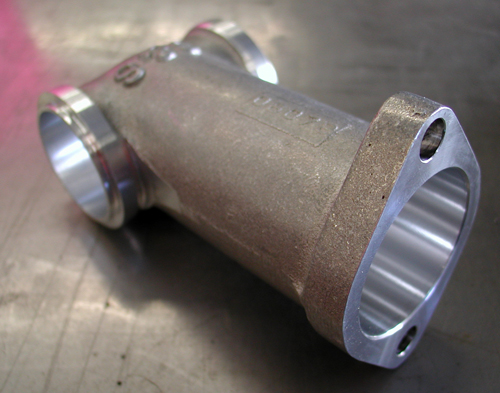
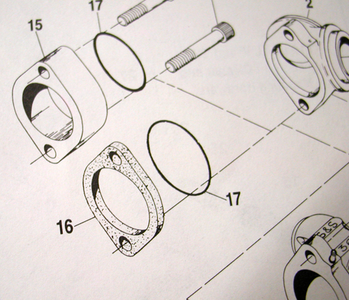
In our case the carb was already removed, so we pulled the O-ring from the back which seals the carb to the intact manifold. We also installed a brand new S&S intake manifold to make sure we had the proper venturi for this carburetion and a manifold designed for the S&S system.
Next I reached out to a factory rep for his advice. Here’s what he said:
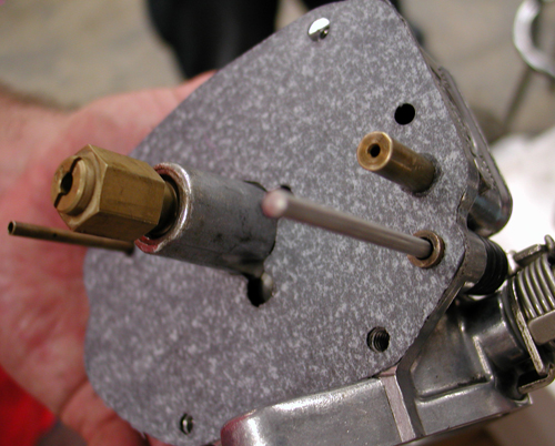
One of the problem areas on any carb is excessive wear in the housing, where the throttle shaft rotates. The old Bendix carbs were notorious for this. The excessive wear would create an air intake leak causing drivability issues and poor idling.
I used to make stainless steel bushings and bore the throttle shaft boss. Then I could press in the bushings and save a carb from being scrapped. I think that S&S has a repair kit for this problem. It may be that you send the body to S&S, and they fix ’em in house, I can’t remember.
We also would run an in-line filter between the tank and carb in the fuel line. This has always been a good idea to keep the shit out of the float bowl. The tank fuel valve usually has a filter screen in it, but they are difficult to inspect. Every now and then I drain the carb float bowl to inspect the gas for particles.
As far as winter storage: I put the Stabil additive in the gas tank. Then I run the bike a bit making sure the fuel additive reaches the carb. I don’t drain the float bowl. In the spring, I flush the float bowl and gas tank after the winter season. Then I install fresh gas, new plugs and start ‘er up, allowing the fluids to warm, then drain all the oils. I’ll then install fresh fluids and be good to go. This worked for me when I lived in Chicago. A very cold place!!
–Pablo
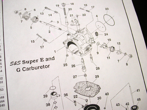
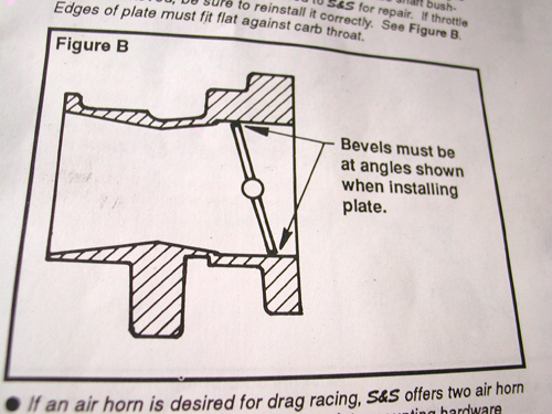
Good advice: If you ever install a Super E or G hold onto the installation guide. It’s fulla helpful information as well as drawings, including a breakdown of the entire carburetor. Currently there is no rebuild instruction sheet, making this kit a basic clean, inspect, and assemble with new components. The install guide does tell you how to trouble-shoot some specific problems.
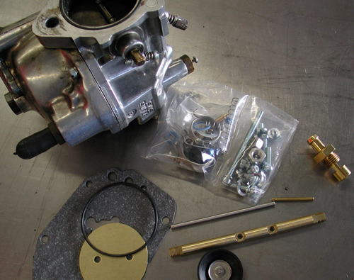
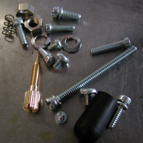
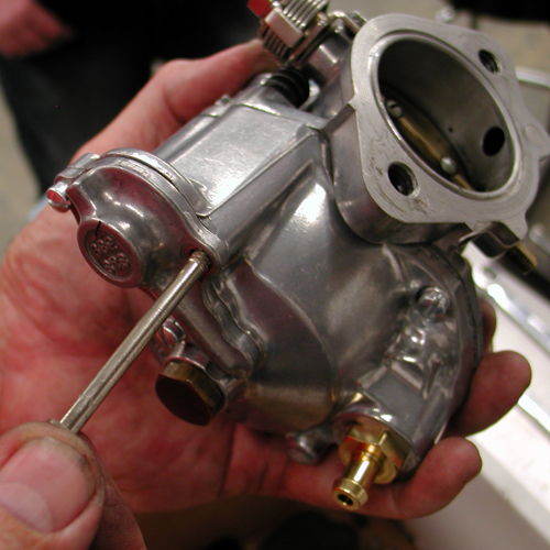
The kit includes nearly every internal part necessary except for the main jet, mid-range jet and the throttle shaft bushings mentioned above by Pablo. As you can see in the photo, all the other elements including fasteners, throttle shaft, butterfly, springs and gaskets are included.
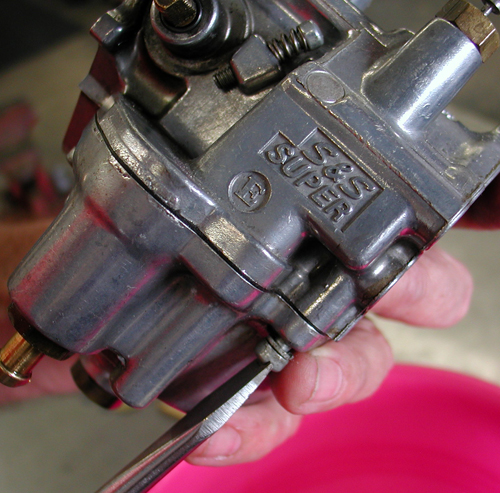
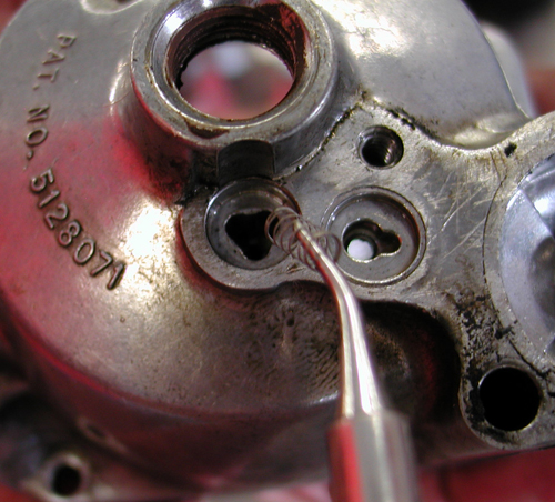
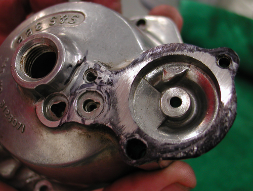
With Brad’s pink parts cup under the carburetor we removed the float bowl, drained the body and cleaned it with solvent. Brad experienced some starting problems and the accelerator pump didn’t work properly, although the bike seemed to run fine once rolling down the road. We researched the Shorty installation and jetting guide for troubleshooting tips. In most cases the problem can be caused with crap in the intermediate air bleed metering hole or the main discharge air bleed metering hole. They’re in the bottom of the carb and can be blown out with forced air once the float bowl and gasket are removed.

Caution: Don’t not use wires or drills to clear holes. If sizes are altered, air/fuel ratios of idle, intermediate and high speed systems will be changed resulting in poor performance. Make sure to wear glasses when messing with compressed air.
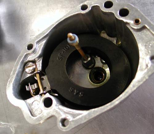
There is also a bowl vent tiny passageway in the bottom of the bowl. It is designed to equalize bowl pressure and atmospheric pressure. Make sure it’s clear or the engine will run erratically.
Problems can also occur when a rider doesn’t use an insulator block between the carb body and the air cleaner. Heat transferred from the manifold to the Shorty carburetor body can cause a temporary rich condition at idle and low rpms when bike is hot.
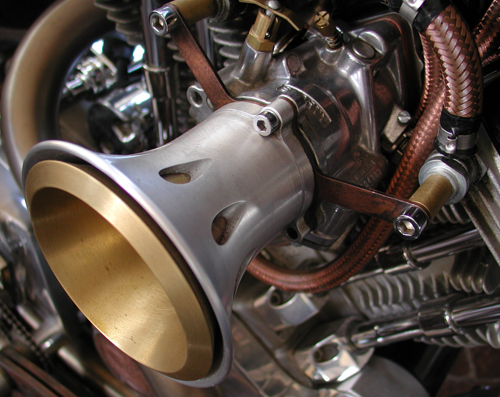
They also mentioned bikes not running air cleaner elements or running velocity stacks are recommend to remove the bowl vent screw part number: 11-2161. It should be removed to insure atmospheric air pressure equals air pressure in bowl cavity above the fuel level.
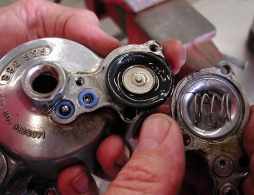
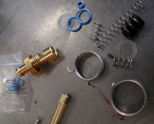
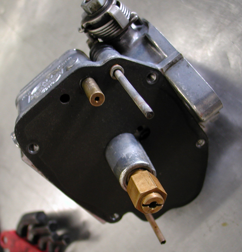
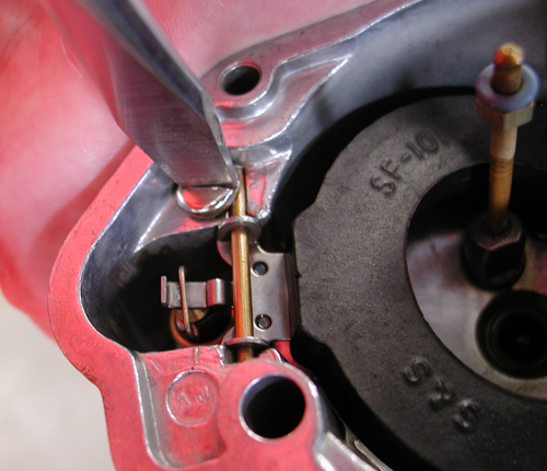
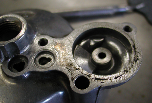
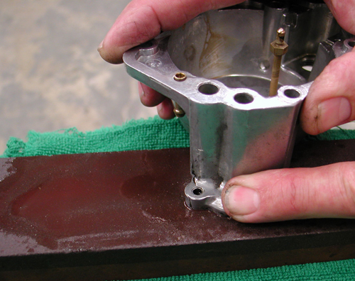
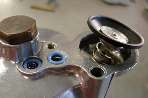
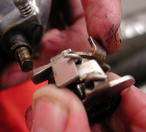
We pulled the float and dissembled it, cleaned it and blew out the passages. Then we removed the accelerator cap from the bottom of the bowl. It holds the two very small O-rings, two dinky ball bearings, a spring, the accelerator pump diaphragm, and ½-inch diameter spring. We cleaned this cap thoroughly and blew out all the passages. We also noted that the cap was severely abraised and needed to be surfaced on a flat stone to remove any grooves.
It’s a real trick to put this puppy back together. At first we installed the spring on the wrong side of the diaphragm. The rubber impregnated fabric diaphragm has a raised edge and it slips into a groove on the cap and the spring is placed under the diaphragm. We used thin shim stock to hold these elements securely into place as the cap was turned over and positioned on the upside down float bowl bottom.

The float bowl could not be turned right-side up since it housed the two dinky check balls and one tiny check ball spring. Believe me, when you drop this puppy everything stops to find it. I started a couple of screws then slipped the shim stock out of place. Then I tightened the new screws.
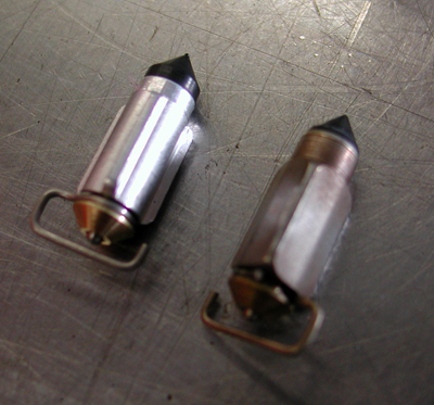


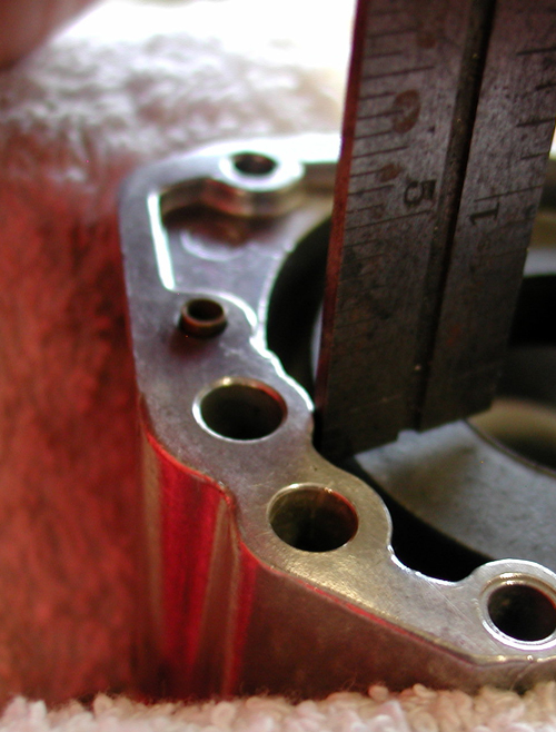
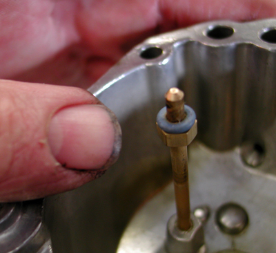
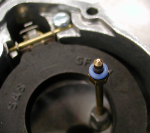
Then we replaced the float with a new float needle and measured the position. It’s supposed to be between 1/8 and 1/16 of an inch below the lip of the bowl with the float needle pressed into place. We adjusted this since it was 1/8-inch out of whack.
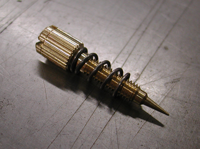
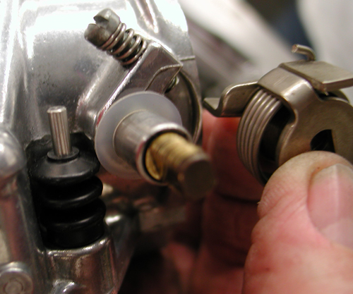
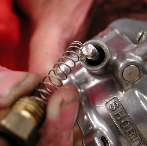
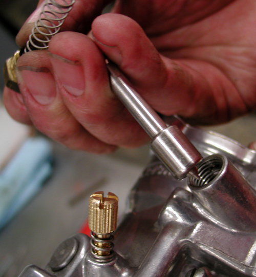
We replaced the idle mixture needle with a new one and it’s spring. We removed the accelerator pump lever and spring to free the throttle shaft. Since it didn’t flop around in the bushings and the butterfly fit properly against the venturi we left the shaft and butterfly alone, but cleaned around them thoroughly.
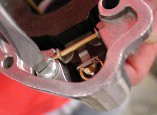
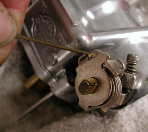
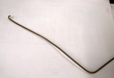
It’s a true trick to replace the pump actuator lever, spring and arm. I finally made a spring hook tool out of brass rod to pull the spring into place. Fortunately we had another assembled Super E on hand to refer to. It’s never a bad notion to take a couple of photos of uncertain areas for reference. This was a good one.
We replaced all the O-rings, cleaned the fast idle components and replaced the accelerator pump shaft and bellows seal. We were getting close.
With the body complete and the float bowl setting aside covered from collecting dust, we installed the float bowl. I discovered a very small O-ring under the original float bowl gasket. We made sure all the O-rings including the ejector nozzle O-ring were back in their proper places.
She was buttoned up and ready to be returned to the classic ’61 Panhead where she belonged. Brad mounted her the next day. “She started on the third kick and the accelerator pump is working like a charm,” Brad reported via the phone.

Starting Procedures:
James Simonelli, from S&S, sent me the following starting procedures, “I like to pull the enrichiner up for prime kicking only, on a kick start bike. Pull it up, key off, two slow kicks, push primer down, crack the throttle, key on, and go for it.”
Tuning tips:
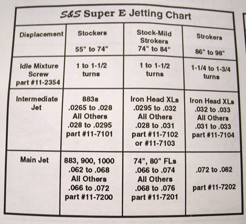
Here’s some tuning tips from S&S for both the Shorty Super E and G carbs. First adjust the idle circuit by adjusting the idle mixture screw, which regulates air/fuel mixture at idle speeds (set it initially 1.5 turns from bottom). Start the bike and let it warm for two minutes with the idle speed at between 800 and 1000 rpms. Turn the idle mixture screw clockwise, leaning the mixture until the engine starts to die. Then turn it counter-clockwise, richening the mixture, until it wants to die again. When the idle mixture screw is positioned about halfway between these points, or about ¼ to ½ turn out from the lean side, it’s set correctly.
If it doesn’t idle properly, check for a leaky intake manifold or bad ignition timing.
Intermediate SystemIntermediate range starts right off at idle and extents to 3000-3500 rpms or 50-60 mph. To test and adjust, ride the bike until it’s hot. Double-check your idle adjustment.
Note:It’s sometimes helpful to shut off the accelerator pump while fine tuning the intermediate circuit as fuel from the pump can mask jetting symptoms.
Check throttling characteristics by slowly rolling throttle on after maintaining a steady speed. This should be handled at several speed levels, like 30, 40 or 50 mph. If popping or spitting occurs the bike is running lean and the intermediate jet must be changed to the next larger size. Repeat the road test.
High Speed Circuit or Main Jet Adjustments:
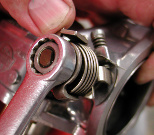
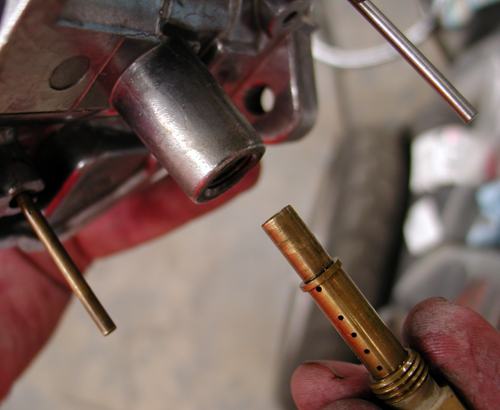
The high-speed circuit kicks in above 3000 rpm or 55-60 mph and operates to maximum speed. The main jet is easy to reach by removing the brass plug on the bottom of the bowl, and reaching inside with a flat bladed screwdriver. The size is stamped on the lip of the jet.
Main jet size is best determined by testing at a drag strip, because maximum mph is the best fine tuning indicator. Okay, so that’s a tough one for most of us.
Street Procedure
S&S uses what they call RPMing method to determine main jet size. Under racing conditions this level is where horsepower peaks and begins to taper off, and is where top speed gearshifts occur. The main jet that makes engine accelerate strongest, or rpm through gears quickest, is correct.
After warm-up, accelerate rapidly through the gears noting how quickly and smoothly engine reaches an rpm level where pull of engine begins to fade and gearshift occurs.
If engine backfires in carburetor and sputters or “breaks up,” and/ or dies during acceleration, increase or richen main jet size .004 larger and road test again. Note engine smoothness and how easily engine reaches rpm level where gearshift occurs.
If engine runs flat and sluggish or “blubbers,” or will not take throttle, decrease or lean main jet size .002 smaller and road test again.
There you have it, the Bikernet S&S Shorty carburetor rebuild and tuning guide. How’d we do? Let us know if you have any additional insight or tuning tips. We’ll be glad to add them and images if you can supply them.
–Wrench