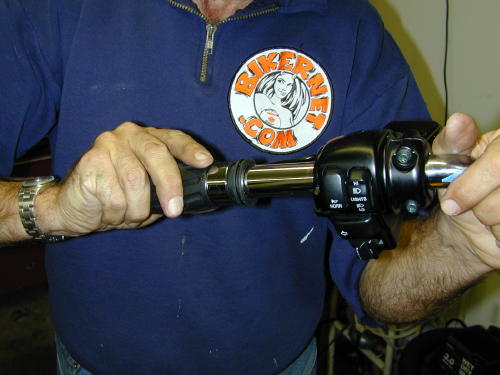
I couldn’t think or speak. I had a week and a half to insure that this puppy ran. I could sense fangs growing under my upper lip. I began to snarl as my fingernail extended beyond my cold hard hands. My eyes reddened, and I wanted to ride. Without the throttle cables I could use the cruise control, if it still worked. I could jam it into gear and fly. Frank hit me with a torque wrench. “We’re burnin’ daylight,” he snapped, “Let’s measure the cables and install the left Knuckle style grip.”
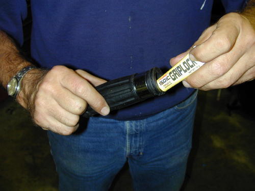
After wiping the grip end of the bar down with alcohol, the grip interior was coated with the rubber cement, that came with the grips. Then it was immediately slipped into place.
I snapped out of my Werewolf London fog. We measured the clutch cable then compared our findings with the throttle cables. As I suspected, lucky 13 inches to make up for the 12-inch taller bars that were an inch wider than the stock units. Frank made a B-line for the phone to call Barnett’s and ordered the cables. We were scheduled to roll up to the fleet center for a performance upgrade on Friday. It was Tuesday and the cables wouldn’t arrive until Thursday. It was going to be a close call. “Barnett has been around since Moby Dick was a minnow,” Frank said. I’ve been ordering custom cables from them since I was in my 20s and first influenced by Apehanger madness. “They are as reliable as the sun on the coast,” Frank continued, but I was still nervous.
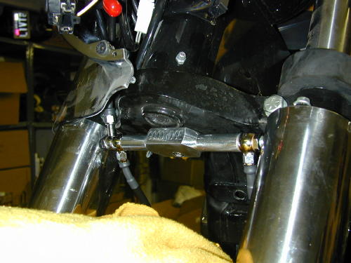
We weren’t done yet. We torqued (15 foot pounds) the bars into place and began to cut and fit Goodridge brakes hoses, distributed by Barnetts and Custom Chrome. Another delicate operation.
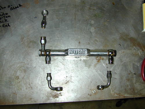
The King has dual disc brakes and the fittings had to be installed just right, tightened properly and finally torgued into place. From the bottom of the triple-trees we used the stock measurement to the calipers from the existing junction under the trees. The new lengths of Goodridge hose were cut with the largest, strongest side cutters I had. Before any fittings were installed we slipped a 2-inch piece of black 3/8-inch diameter shrink tubing over the hose. Next a chromed pinch fitting was slipped over the cable. Frank brought the tools and supplies including a tool to spread the braided hose after the rubber housing was stripped away to allow the new fitting to be installed.
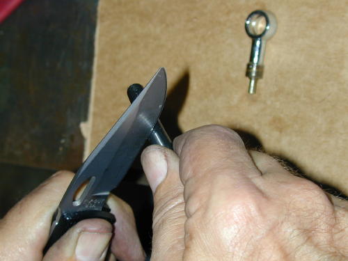
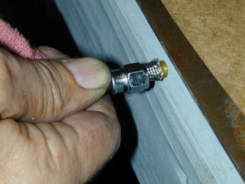
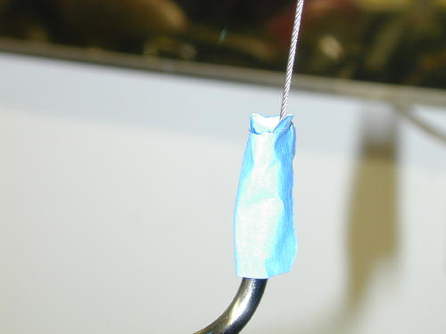
Stripping the rubber sleave back from the end about an inch.
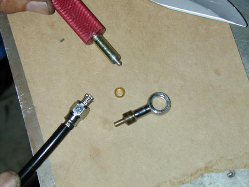
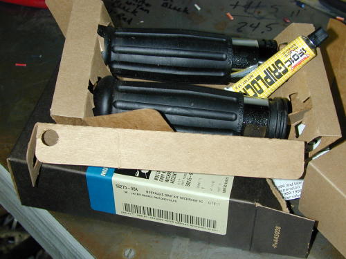
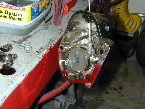
Here’s all the components involved in the process.
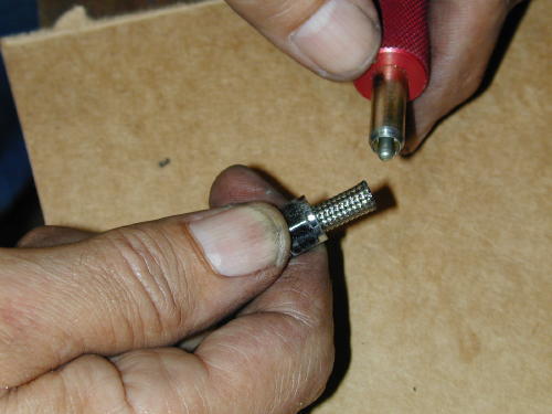
The tool used to spread the braided steel shield.
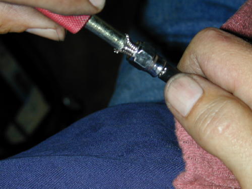
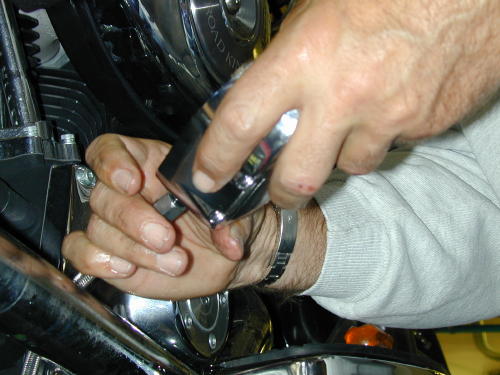
Then a small brass round furl (like a brass ball-bearing with a hole in it) is slipped over the plastic lining. It must be pushed to the point where the internal brass ridge meets with the end of the plastic liner. The other half of the fitting with the long tube is shoved into place. In each case we clamped the fitting between two sheets of leather then began to tighten the sleeve onto the fitting. In each case they were a bear to tighten down indicating that we had succeeded in a strong, secure grip.
The spreading process involves shoving the tool into place and swiveling it to make sure the braided area is spread consistently.
Installing the furl is simple, just slip it on carefully then push it into place. But, inspect the inside to make sure the plastic hose is against the interior ridge.
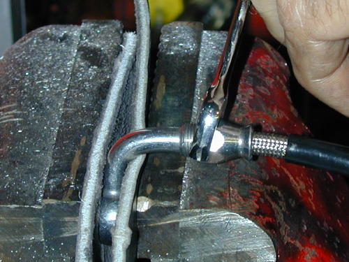
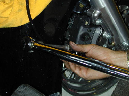
Now tighten the pinch fitting. Note the leather pads in the vice to prevent damage to the banjo fitting. These puppies are tough to tighten down, take your time.
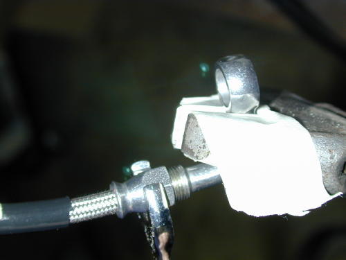
Here’s another way to hold the banjo fitting for final tightening. Be careful not to bend or damage the sealing surfaces.

Note the two bronze washer/gaskets on either side of the banjo fittings for proper sealing which is critical to your brakes.
After each line was carefully constructed, they were installed on the bike after some jockeying with the Goodridge billet junction under the tree which fit precisely.
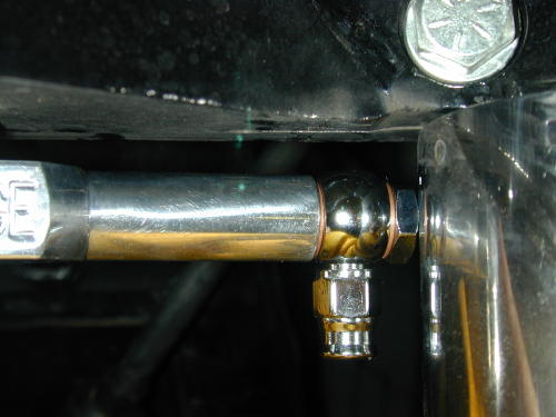
For some reason, this Goodridge junction mounted extremely snug between the fork tube guards. For awhile we thought we were in trouble.
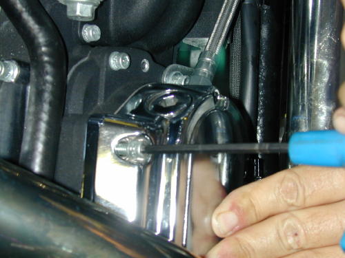
We followed the original routing of the stock brake line through the nacelle. With the lines in place we torqued them down (17-20 foot pounds). I took the easy way of bleeding the brakes. I pulled on the lever gently allowing the bubbles to pass through the master cylinder. It took a while, and I had to keep filling the reservoir as the the lines drained the supply.
We used the stock 12-point fittings which torqued down easily to 17-20 foot pounds, which seemed like a lot.
We had completed all that was possible for Tuesday and I swung my leg over the saddle once more. As fire and smoke poured from my ears Frank crept out of the garage and into the night.
Thursday morning I paced the vast porch in front of the headquarters waiting for the UPS man. The truck sped past without a hint of slowing. I called Frank, he called Barnetts. I called the Fleet center after finding that the cables wouldn’t arrive until Monday morning, guaranteed. We had an American Rider magazine deadline, but more importantly I had a run-to-Arizona-deadline for the following Friday. I started pacing the garage and bowing to the new 16-inch apes. I knew, by the power of the Ape, we would succeed.
At 9:00 a.m. in my boxer shorts, Monday morning, I met the UPS man and signed for the Barnett package. I started to lube all the cables then decided that I should get dressed.
In order to install a new clutch cable the face of the transmission must be removed. I was surprised that this was the first item that I ran across on the King that was a pain in the ass to install. The entire exhaust system had to be loosened all the way back to the rear muffler isolator. before the clutch release housing could be removed.
With large clip ring pliers the throw-out mechanism was set free to release the clutch cable which virtually snapped into place. Then the cover was spun to allow the cable housing to unscrew. Next the new cable was fed along the same route as the stock job.
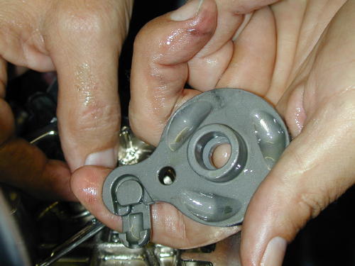
Once the clutch release cover is removed and the clip ring snapped out, you can see the outer ramp with the coupling ready for the cable.

If you look close the cable has been fed through the hole and is heading towards home.
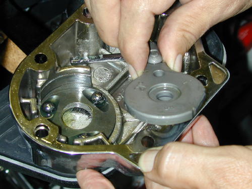
Now with the new cable attached the outer ramp heads back into position. Watch you don’t tilt the case. The ball bearings will escape.
This shot shows the entire clutch release assembly complete. Remember as you reposition the clip ring to put the sharp edge up for the most secure bond.
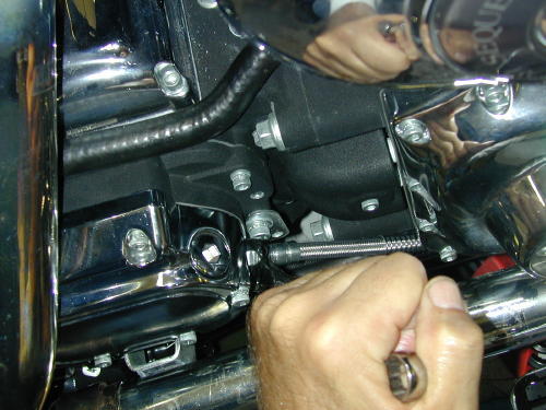
We discovered that we had a lot of slack and rerouted the clutch cable outside the front motormount to eliminate some. Then the tranny cover gasket was wiped clean and the cover replaced (torqued to 10-12 foot pounds), then refilled with tranny fluid to the appropriate level with the bike upright and the dipstick threads just touching. We filled it to the top dipstick mark, about 3/4 of a quart capacity.
With this assembly you spin the cover onto the cable, not visa-versa.
According to the book, the torque specs call for 10-12 foot pounds of torque to snug up the clutch release cover.
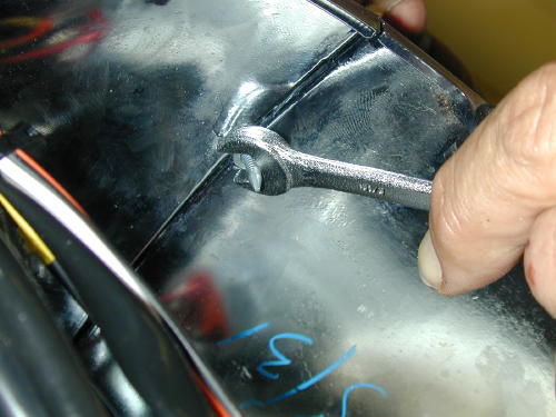
With a 9/16 box end wrench snug the cable housing down with a new o-ring attached.
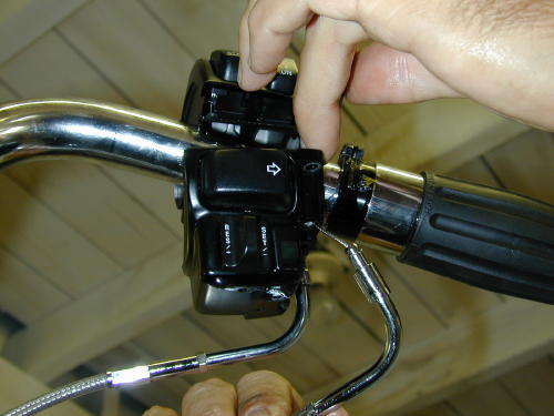
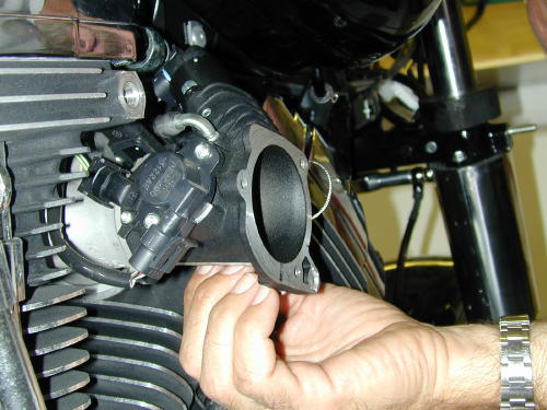
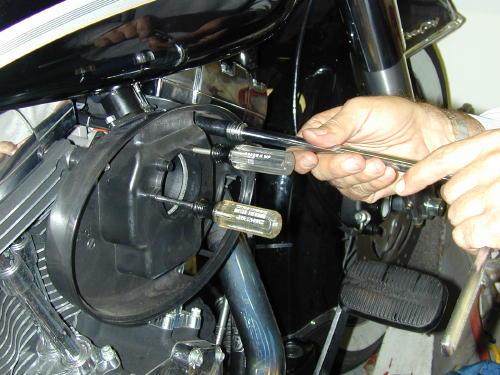
We jacked-up the gas tank to afford us access to the fuel injection throttle cable routing. With the three tank mounting bolts removed the tank was lifted easily until a chunk of wood could be wedged under the front of the tank. Then I figured out which cable was what. With a small Crescent wrench, I loosened the throttle cable adjusters and took out all of the adjustment to allow lots of cable slack.
The unit with the small spring around the cable at the throttle body end was the push cable. I fed the braided cables through the runners as if they were stock cables. You will note, if you attempt this, that there is a Cruise Control connection in one of the stock cables at the neck. We unplugged it with trepidation. I wasn’t sure what havoc it would cause. I hadn’t tried the Cruise control. As it turned out, it’s a sensor to kill the control, if you back off the throttle abruptly.
Lubing throttle cables starts with wrapping the cable housing with a little masking tape to create an oil container. Fill it with a light 3-in-1, silicone, or Marvel Mystery oil and let it seep into the housing. Fill it several times.
Feed the cables up through the throttle casing. With a little force they will snap into place.
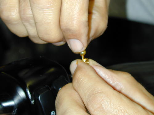
Make sure to grease the brass barrel before installing it to the cable end. The grease will help hold the barrel in place.
With the Barnett cable set at the most slack position, slip the barrel and cable onto the greased throttle guide grove.
This is not a good shot of installing the cables into the guide slots in the intake module, but it’s easy. Just make sure you have the right cable in the right slot. It doesn’t hurt to grease them which we forgot.
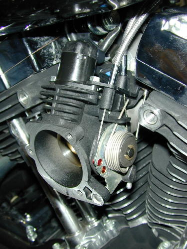
Here’s the cables in position. That odd short cable on the side is the cruise control job.
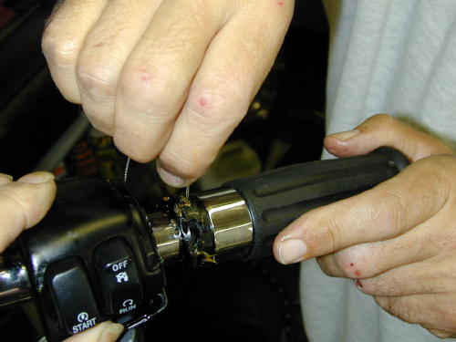
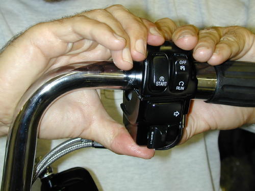
Make sure you oil the throttle cables before they are snapped into the throttle housing on the bars, because the spring clips that hold them into place are a bitch to remove. The cables were both put into place with brass rollers, “After you grease the throttle and cable runners with a Q-tip,” Frank reminded me. Be careful not to lose those tiny brass suckers. I was told later to try to adjust the cables evenly under the throttle and make sure you have slack in both lines so you don’t have continuos drag on the cable fittings.
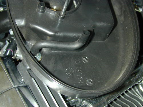
Here’s the throttle body in place waiting for the front brake mastercylinder.
According to experts, you should adjust the cables so that the adjustment screws are approximately equal in length. My adjustment had to be straightened out at a later date.
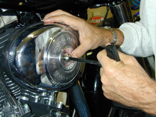
Finally we replaced the air cleaner backing plate using Phillips screwdrivers to hold the gasket in proper position. Next the breather hoses had to be pushed onto the head fittings and lined up with the air cleaner element. Lastly the cover was installed. It was time to ride.
But not so fast Kimosabe. We had to install the riser cover, the nacelle trim and the headlight assembly. We were hauling ass.
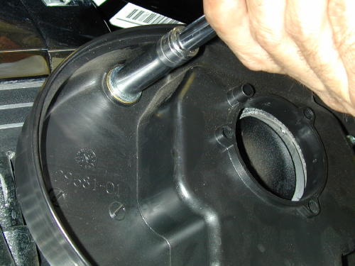
The actual breather fittings hold the air cleaner backing plate into place.
Use small Phillips screwdrivers to hold the air cleaner gasket aligned.
Push the hoses into place keeping in mind that they feed into the air cleaner element.
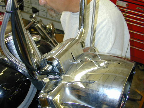
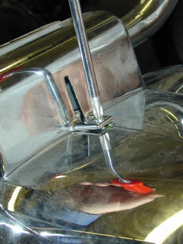
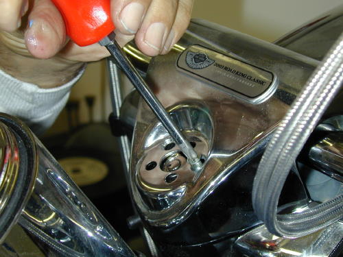
This little nut and screw are a bear to replace but must be handled before the nacelle strip can be installed.
This slightly out-of-focus shot shows the little stud that slips through the nacelle. Make sure the strip is locked into the riser cover slot before you tighten the nut.
Tighten the nut lightly with blue Loctite to keep it from rattling loose.
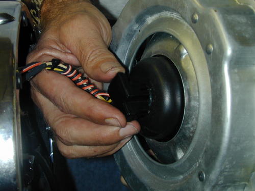
Don’t forget to plug the headlight in before you install it, like I did.
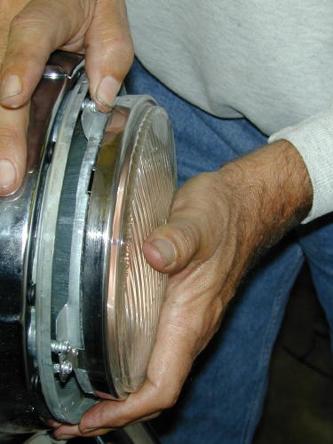
Install the headlight assembly with all eight black screws. Leave the bright adjustment ones alone, unless you lowered your bike. Then it needs adjustment.
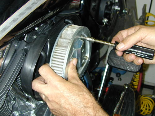
We could screw the riser down with the Phillips screws and replace the snap-on ignition ring last. I still don’t like the way it fit and need to check it again.
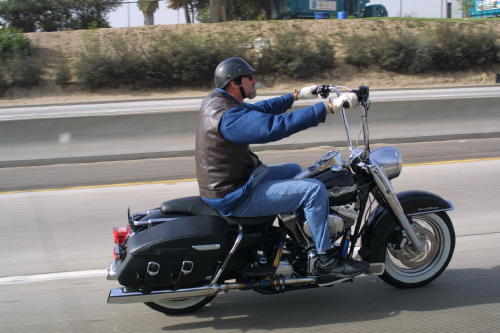
By noon on Monday we had completed the Highbar installation and I was itching to hit the road. We had moved our appointment at the fleet center from Friday to Monday morning, then to Monday at noon. We didn’t roll up to their doors until 1:30 p.m. and Alan, the master mechanic announced that he was leaving at 4:00. We were burnin’ daylight once again. Would the pressure every end?
The final Frank shot with one hand hanging outside of a van window. I want to thank Frank for the use of his tools and his photographic and technical skills. Those elements and my bumbling hands make these techs as complete as they are. Believe me, it’s a bastard to build a bike, write a tech and take the shots at the same time. We’ve done it before, but a team efforts helps a helluva lot.
Next, we’ll install a performance package with Screamin’ Eagle heads, cams, air cleaner and two into one exhaust that we had jet hot coated. Hang on.
–Bandit