

There’s an unwritten rule in the Code OfChrome that says, if you slip a set of highbarson any motorcycle you save it from mediocrity.There’s more, an evil punishment for this oftenillegal gesture towards the rebellious arts. Assoon as the unsuspecting rider throws his legover the saddle and reaches for the tall grips,his sideburns expand down the sides of hisface and a goatee springs forth from his chin.The cuffs of his t-shirt roll, and he begins tosmoke a pack a day. An treacherous grinspreads across his smoke tainted teeth, as ifa deadly rash, and before the week is out he’sleft his lovely religious wife and ravagedseveral other women. Hearts lie broken in histire-burned path. It’s an ugly sight. So what didwe do to the King next–Highbars to the stars.
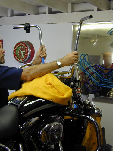
As soon as a date was set for theArizona Run I called Frank Kaisler, “We’ve gottwo weeks. Let’s install the highbars.”
“You’re nuts,” Franks said, “but we allknew that. Let’s do it. Make sure you have aroll of thin 60/40 solder, soldering paste and awide variety of long shrink tubing from 1/8 to1/2 inch. Oh, and you can get a head start bydrilling holes in the bars for the wiring and aslot at the bottom for the wires to exit. Startsmall and work up to and beyond 1/2-inchholes.
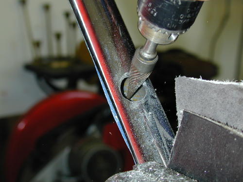
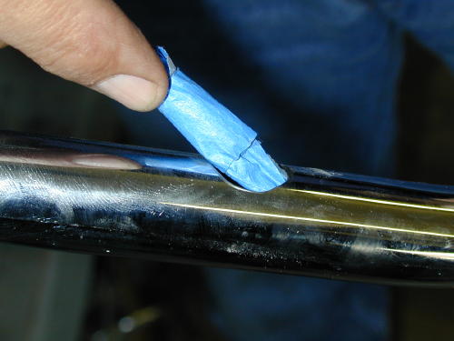
With multiple drill sizes and burr bits Iformed over 1/2-inch holes after holding thebars up to the bike and trying to estimate theposition of the grips. This is critical. I unboltedthe grips and measured the distance in fromthe end of the bars where the wires would runand noted the position of the wiring.
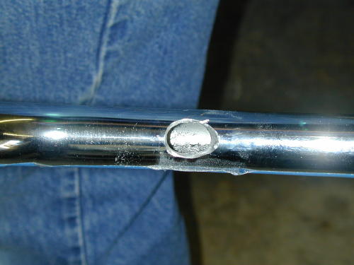
This was nervous work since it was notprecise. Even the slot at the bottom of thebars almost 2 inches long and 5/8-inch widehad to be carefully positioned not to put unduestress on the wires.
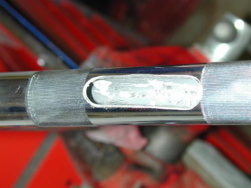
I took the riser housing off so I could seehow the wire looms and cables ran. WhenFrank arrived he brought along a sack full oftools that included emery bits and a dremeltool to smooth out the sharp edges particularlyon the inside.
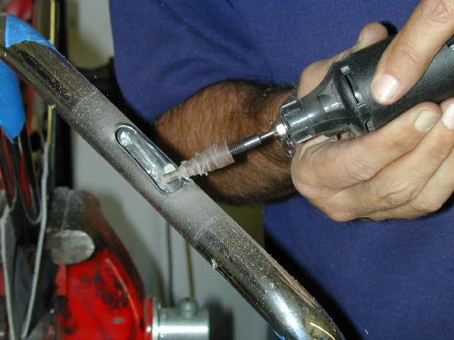
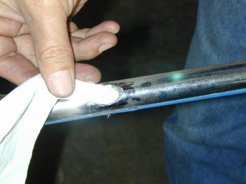
We quickly rounded out the edges of theholes so as not to cut the wiring. Frank usedhis trick of shoving a tissue paper in each holeto test for sharp edges or burrs. If it snaggedthe least amount we continued theedge-softening procedure. He also kicked meduring the process and reminded me todisconnect the battery.
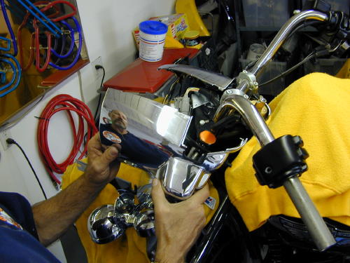
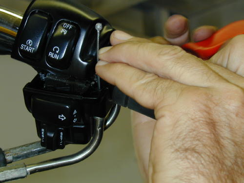
Next we had to carefully strip theheadlighthousing and handlebars. To remove the riserhousing there are two screws adjacent to theignition switch (pop off the guide ring aroundthe ignition switch with a screwdriver), but thatdoesn’t do the entirejob. The headlight ring must be removed.Take the sheetmetal screw out of the bottomof the ring and then lift out and up. Thering is held by a notch at the top andsupported by a spring that will snap loose.When it pops free there are eight small blackscrews holding the headlight assembly inplace (the other silver screws are there toadjust the lens–don’t mess with them). Afterthey were removed theassembly came out easily but needed to beunplugged from the wire connection at therear.
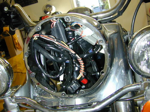
The wiring seems daunting, but it’s notbad and very organized.
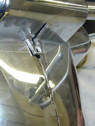
The last small bolt holding the risercover inplace goes in this hole under the nacelle strip.The strip hooks into the slot above it.
Then you need to reach up under thecowling and feel along the bottom for the verysmall nut that holds the bezel strip in place.Once the strip is removed, the riser cover canbe removed.
Here’s the cover removed. A lot of workto reach the handlebar clamps.
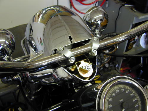
The two 5/16 dome nuts holding eachside of the bezel also hold the runners for thewindshield and the passing light bar, whichwe removed along with the front crash bar–Living dangerously.
Then the passing and turn signal light barwas removed for ever more, and the bezelremoved with the 5/16-inch dome nuts oneither side of the front end (make sure youkeep all the fasteners together including thewindshield runners). Set the chromed bezelaside somewhere out of harms way. That’s abig chunk of visible chrome.
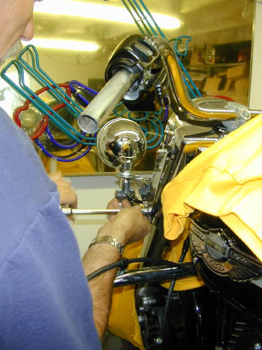
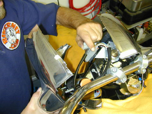
This photo reveals a handlebar clampbeing removed. It’s bullshit. We didn’t removethe handlebars until much later.
If you have a pal in the garage drinkingbeer and watching, get him to take shots ofthis process. If you must wait a week tore-install all this crap you may need areference guide and photos help a feeblememory. Or, of course, come to Bikernet andprint out this tech. Don’t forget to cover the tankand fender with something soft to protect themfrom scratches.
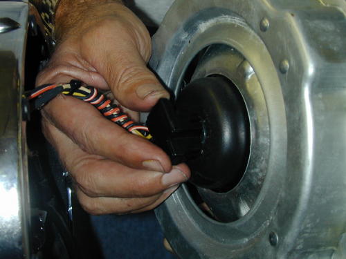
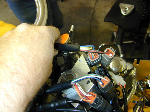
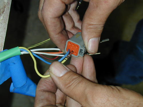
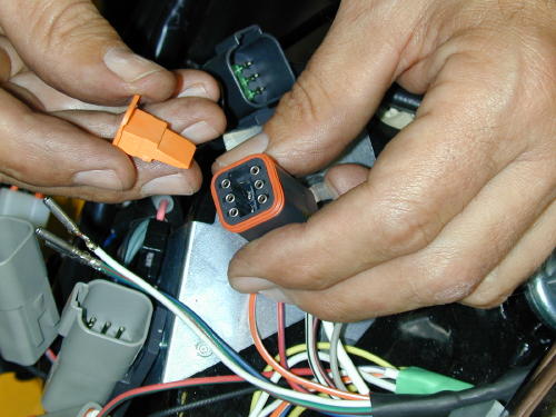
We noted that the electrical plugs on theleftside of the bike were different color from theright. We also noted their location and thedistance from the bars were measured beforeunplugging each connection to the handlebarswitches.
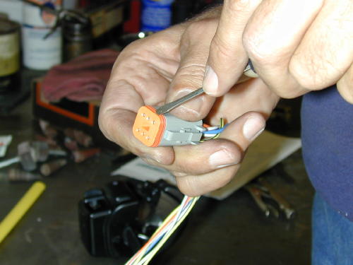
Don’t remove any wires before youdraw the diagram below. This cap performs acouple of functions. It seals the plug andinternally is pinches each wire lug in place.Once it’s removed a small screwdrive will pulleach catch away from each individual wire lugso it can be removed easily.
Check your diagram twice, no threetimes, before removing any wires.
We also noted the position of the throttlecables before removing the bars. Then thegrips were removed and switch housingsloosened so we could begin on the left side ofthe bars.
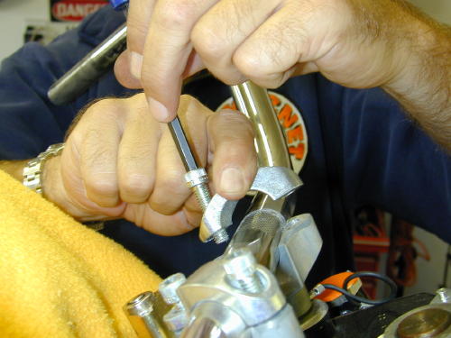
We handled the left wiring extensionfirst. This shot is of the right side and doesn’tshow a helluva lot, but it’s important. Toremove the throttle cable housings from thethrottle body it takes four miniature hands andtwo dinky screwdrivers to pinch the spring ringthat holds the cable in place. Be patient.
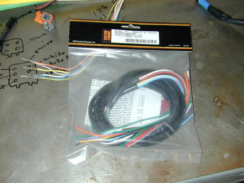
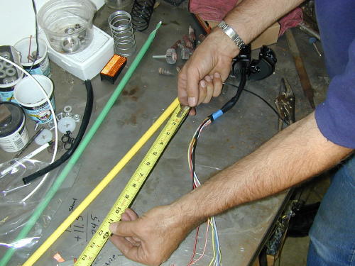
We measured the length of the wiresfromthe switches to the plugs, then compared thatmeasurement to the new highbars anddetermined that we needed to extend thewiring 13 inches to insure the proper length.Add an inch just for safe keeping. This aspectwas measured carefully several times.

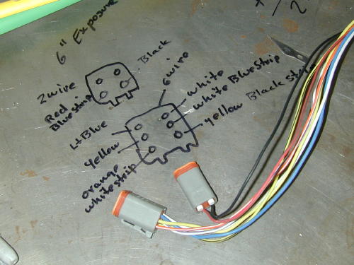
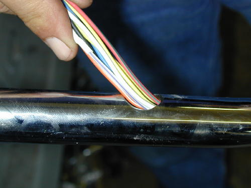
Then the left switch loom was attackedfirst by drawing the back of the plug on thestainless bench top with a felt pen. We notedeach color coded wire and position beforeremoving the wires from the plugs. Do it fromthe back so you’re in the same position whenyou reinstall the wires.
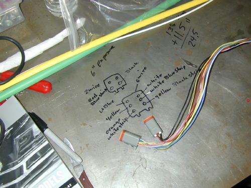
Sure, here’s another shot of a diagram,but it’s damn critical to insure the wiring iscorrect, so pay attention. Note, that we madeindications on the drawing to indicate the topfrom the bottom of the plug.
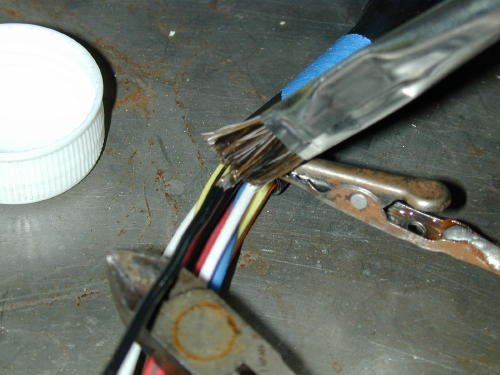
We added sections of 13-inch wirestaggered in the center of the loom so as notto stack junctions, and so we maintained theoriginal color coding. Each junction wascarefully striped 1/4-inch, soldered and sealedwith shrink wrap.
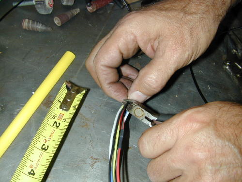
One shot we missed depicted thewires staggered. That’s also crucial so youdon’t have junctions bunched together.
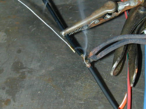
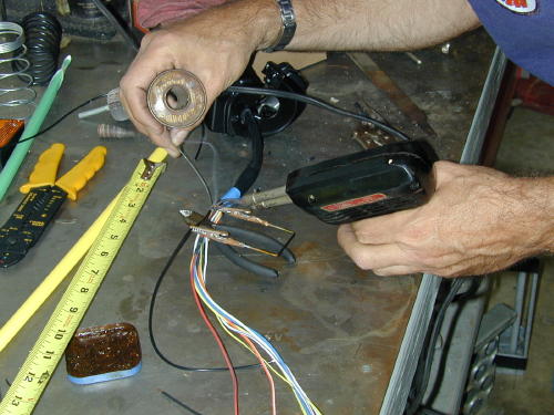
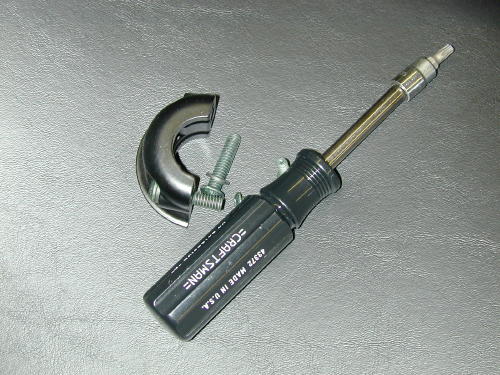
Note the handy wire connection holdingtool that Frank had made while working alonein his garage for ten years. Trying to hold theconnection together, while holding the solderand the gun is nearly impossible.
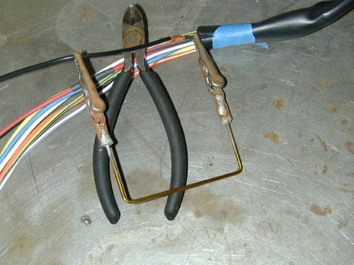
The Frank Kaisler, patent pending, wirejunction tool. Send $99.99 to P.O. Box 666,Hollywood, Calif. Send only rolls ofquarters.
He spoke to an engineer at one point whodidn’t cotton to twisting wires. He suggestedthat the wires be carefully mated straight onand soldered. The “Puerto Rican shrink wrap”as Frank refered to my colorful array of shrinktubing, was cut so that it would seal 3/8s of aninch on either side of the connection. Mostchunks of 1/8-inch diameter shrink wrap werea pinch over an inch long.
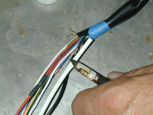
We also washed each connection withalcohol to remove the flux, which could harmthe wires or insulation, then with wet and drysandpaper, brushed any sharp edges thatmight cut through the shrink wrap.
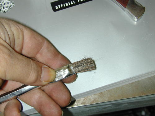
We cleaned the connections usingalcohol with this brush trimmed in half tomake the bristles stronger.
After each wire was carefully soldered andprepped we covered it with shrink wrap, thenusing Frank’s handy tool we heated the areaand moved onto the next stage.
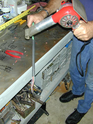
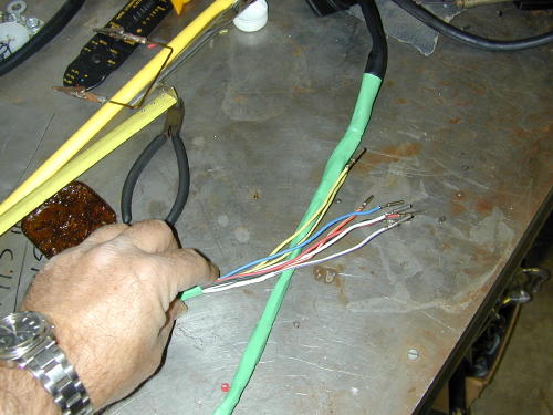
Then the looms were carefully coveredwithadditional 1/2-inch shrink wrap. Finally thebars were carefully blown out with the aircompressor and wiped clean before thelooms were fed into the grip ends of the bars(first we wrapped the pin connections withpainter’s masking tape and created a guidingpoint).
I used a painters masking tape to wrapthe connections and form a guiding point. Ididn’t want to use a tape that would requireawkward or violent stripping to remove it(which could damage the wiring).
Feeding the wiring into the bars fromthe grip end.
Once carefully pulled through the bars andthe switch housings positioned, we beganthe process of installing the connector pins.
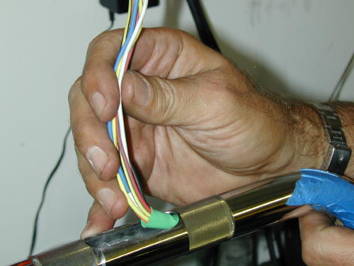
Gently pulling the wires from thebottom of the bars.
After making sure the wires are exactlyin the right position we snugged down the torxscrews, but not permanently.
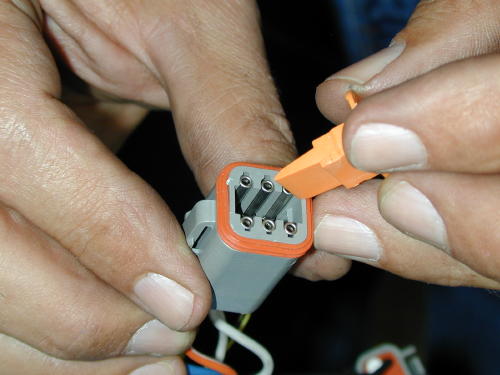
While refering to the diagram on thebench we carefully replaced the wires in thebottom of each plug.
Note the wedged caps that force eachwire clip into a locked position.
This depicts the same procedure fromthe other side of the bars. What a great shot,huh?
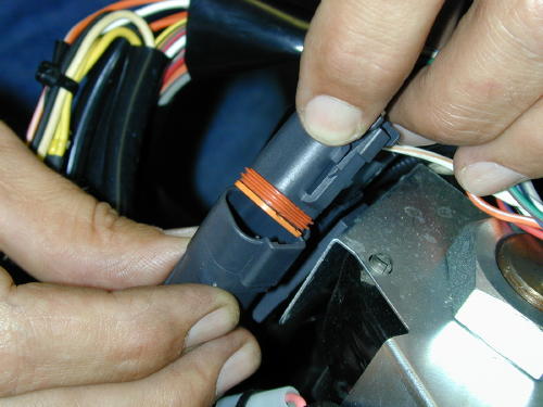
Only then could we snap the plug backinto place on the bike. Of course the plugcolors matched.
This was a nervous time. We hadextended 8 and 9 wires respectively (on eachside of the bars), carefully worked themthrough the bars and guided them out thebottom. As we replaced the plugs the sweatbeaded on my brow. Had I correctly solderedeach wire? Was each wire replaced in theplugs properly? Did I call a wire white withgray stripe, when it was actually white withblue stripe? It had taken almost four hours tocomplete the operation on the left side of thebars.
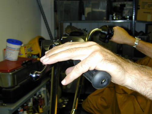
We put the levers in place just to checkthe position and see if we didn’t blow it. It wascool.
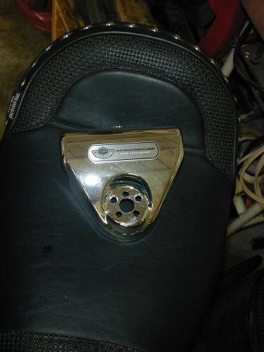
After a needed lunch break we tackledthe right side of the bars with the sameprocedure. Now with the wiring installed in thebars they were returned to the motorcycle. Iswung my leg over the 100th anniversaryCobra-styled seat and perched my ass down.Frank turned the ignition switch on, “try it out,”he said.
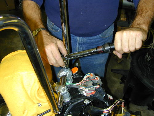
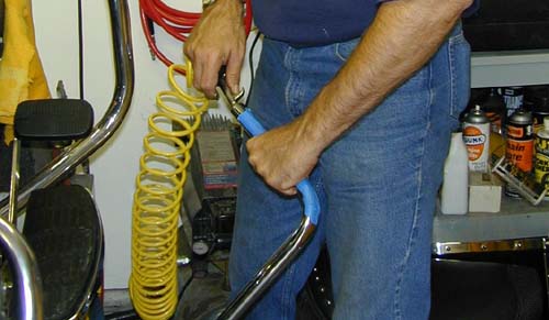
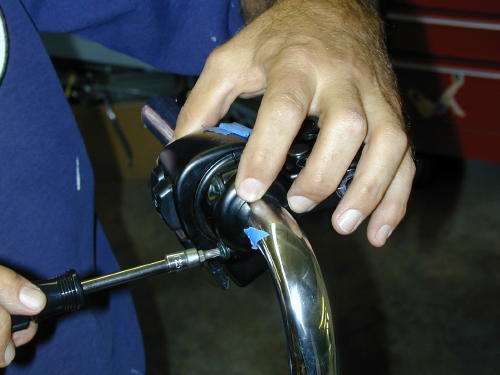
Torquing the bars down to 15 footpounds. Torque the front Allens down first,then the rear according to Pablo.
Continued On Page2