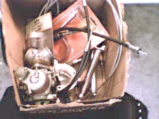
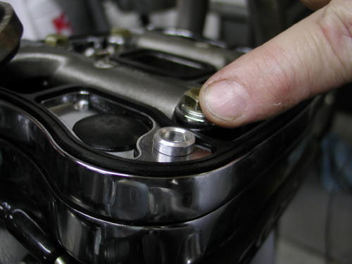
This here cardboard box full of odds and ends was where it allbegan. Or was it just an idea? Or maybe too much Jack Daniels. Ormaybe Bandit was tired of me whining about it. Anyway, like a beggar on the streets ofCalcutta, or Blanche Dubois in “A Street Car Named Desire,” I depend onthe kindness of strangers. And there ain’t none stranger than Bandit’scohorts. Strange but mighty generous, such as Rogue, who cut us adeal on the FXR frame and forks. We’re relying on Joker Machine forall the quality components including the end caps for the swingarmto get this puppy on two wheels.
We couldn’t figure out what this chopper was going to be. Maybe thedefinitive Rat Bike, or a stretched-out steel spider with a hellishV-Twin, or whatever kind of Rube Goldberg, slapped-togethermonstrosity we stumbled upon.
The critical thing is that I’ve got short arms and legs (kind oftroll-like) so whatever we made, it had to have a low center ofgravity. I tried riding Bandit’s Buell, but when I came to a stop, myfeet didn’t touch the ground. So we agreed that the frame had to damn nearscrape gravel. I kind of fancy myself an iconoclast, so I didn’t want tobecome another ad for yuppie motorcycling. Bandit wouldn’t let mepour acid on the thing to give it a lived-in look. If it was going to be a Rat Bike, heproclaimed with bombast, it had to be cool. Well, cool and twobucks might get ya’ a bottle of warm beer. I was determined to make my mark,rat-assed or not.
Bandit suggested that we chop a couple inches out of the frame.
OK, I sez. Bobbed fenders? Bob’s yer uncle, I sez. Narrow the fender railspace? Narrow it is, sez me. Now we’re rockin’. But to tell ya thetruth, it’s still a frame sittin’ in mid-air and a box full of used parts.
But don’t count us out yet. We’ve got a sizzling summer approaching,I’m outta work (I ain’t teachin’ summer school), the Jack Daniels is flowin’,and we’re fillin’ up more cardboard boxes. Bandit’s a tolerant guy, he’s gotthe summer (if he don’t go sailin’ off to the seven seas), and me? I got abrain bubblin’ like a pot o’ hot chili. No tellin’ where thiscrazy-assed bikeis gonna’ take us.
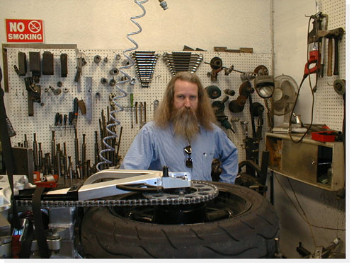
We threw the potentially radical chopper that Bandit and I have banged together up to this point, into the back of my pickup and jammed over to see the Doctor. Dr. John, the frame doctor took one look at the bike in the back of my truck and shook his head. Behind that scraggly beard and those beady blue eyes there is a wealth of experience. He’s seen a lot of biker hopes and dreams, sometimes nightmares, come through his Anaheim Hills shop. He’s managed to salvage most of them. His wry humor snuck through that tangle of beard, “Hmmm, that’s one nice looking Rev-Tech engine.” Bandit ground his jaw, I fidgeted, kicking at the asphalt.
He looked at our hopeful faces and didn’t want to disappoint, “Ok, I’ll take the challenge, but it’s going to take me a couple of days to figure out how the hell I’m going to hammer this thing into shape.” Bandit and I smiled, knowing that the Dr. was going to save our scrap-iron baby.
The whole idea was to shrink the Pro-Street frame around the engine, with just a slight additional rake to the front end. I’m 5’8″ but with short arms and legs, so we wanted the bike frame to be custom fit to my body- frame proportions. We had been looking at some of the bike designs from Japan (where the guys are built more like me) for inspiration.
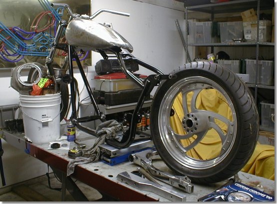
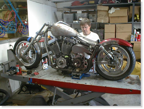
Just with the modifications that Bandit and I have done so far gives some hint as to the unique feel of this design. With the massive Rev-Tech 88-inch engine and 6-speed Revtech transmission squeezed into place, it looks like a Star Wars space sled. I kind of like the rusty, unpainted Pro-Street frame. It gives it an elegant rat-bike look. But then that’s just my twisted sense of humor.
With the rubber-mount engine we have to leave some room for wiggle, so the frame can’t fit like Saran-Wrap. Cutting an inch or so off the swing arm will bring the back tire teasingly close to the inside-front of the swing arm. With a tiny back fender and stretched our front, the ass-end of the bike will look like it’s tucked in below the seat. I said it’s going to look like a running, weird-assed wild hyena. Bandit didn’t care for the comparison and shook his head discustedly.
When we built the Blue Flame, the whole bike was engineered to fit Bandit’s stretched-out body dimensions. Not every bike rider is built like that gangly orangutan, Bandit. So we’ve put a lot of thought into the design of this bike, in terms of scale and proportion. Even the choice and location of foot pegs, shifter, brake pedal, style of handle-bars, and primary shield, will reflect these concerns.
While the doctor is bending and welding the frame into shape, we will be working on paint design, tank and fender design, and ways to clean up some of the wiring, break lines and cables. Or maybe we’ll just fuck off until the doctor calls. Hey, it’s summer and we need to mellow out some.
The day started moderately okay. Bandit and I were going to zoom up toIrwindale to talk to Geoff Arnold at his Joker Machine headquarters to order a raft of parts for the Shrunken FXR, then toAnaheim Hills to meet John the Frame Doctor to check out the progress on myframe, we thought we might also catch lunch with Scooter, our notorious Bikernet criminal attorney, then a leisurelyglide back to San Pedro. No sweat, you say?
The closer we got to the foothills, the morning mist mixed with thecarbon monoxide of a million or so cars careening all over the L. A. basin.Ocean breezes pushed this toxic stew into the eastern edge of the foothills.By the time we got to Irwindale, the Bandit and I were like a couple ofbreakfast eggs sizzling in a skillet.
Bandit called the Doctor to confirm our plan to pop by. No way, no how,says the Doctor. He’s having a PMS kind of day. He hasn’t started on mybike. He’s got a hemorrhoid of a project to hammer out before he can starton mine. Dr. John also repairs sportbike frames and reported that sometimes the frames are so mangled that, well they should be shredded, not repaired. He was up against one of those. So no doctor visit.
A call to Scooter gets about the same results. He’s got to work so nolunch. The day was starting to feel cursed and doomed.
So we knock on the door of Joker Machine. On the other side of the doorwe could hear the banshee howling of an animal possessed. As we walked in,Studley the Joker mascot, attacked with teeth bared, an upper lip curled inschizoid disdain. The rabid Chihuahua snarled, yapped, barked and yelped ina psychotic frenzy. Damn near took Bandit’s arm off when he bent down to patthe little demon on the head.
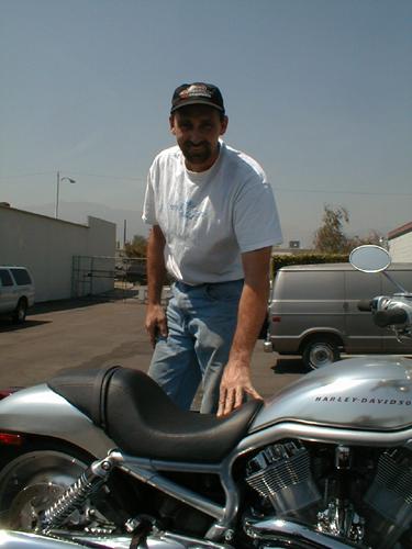
Geoff grappled with the chain, holding back the crazed critter andwelcomed us with a hearty handshake. Geoff was a gracious host, showing usall the latest Joker products and a few of the Joker toys including their new truck.
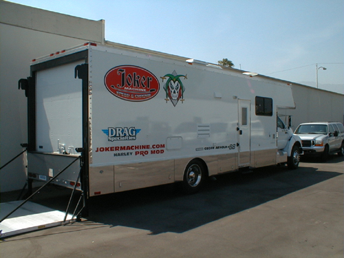
Joker’s new Renegade traveling drag racing garage and party room.
Brian was outside welding together what appeared to be girders for abridge. It turned out to be the sturdy ramp superstructure for the improvedJoker Machine stationary Dyno. Like everything at Joker Machine, expertise andquality construction dominated. That’s one reason we chose to use Joker controls, footpegs and aircleaners and their new rocker covers. The blue flame was domintated with Joker components primarily due to fit and finish. Bandit has never purchased a Joker part and had to modify it to fit.
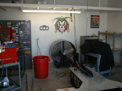
Secret Joker Dyno testing facility. What will they think of next?
Joker is in the process of developing a testing facility for a new line of products, yet to be released to the public.
Over lunch and beers we discussed our design ideas for the new bikesBandit and I are working on. The crew of Joker Machine looked at each othercautiously as Bandit babbled vague musings about “design integrity” and”hidden exhaust systems” or “creating a dense engine compartment.” I chimedin, gesturing with my hands, waving my arms to demonstrate the contours ofthe frame and tank.
Geoff grinned and said that he thought Joker Machine was up to the task.Bandit laughed and said that we had planned to integrate a number of JokerMachine products into our new bikes. Joker Machine, Bandit said, is the bikeparts distributor of choice. For example, he said, products like theadjustable foot pegs allow for adaptation to the individual rider needs.
In addition to the adjustable foot pegs, we intend to integrate into ourdesign with Joker Machine tear drop vents, hand controls and a Joker air cleaner. Weplan to modify Joker Machine forward foot controls to mid-controls.
The Joker Machine crew grudgingly finished their beers and got up toreturn to work. We all walked out side to a blast of heat that would curlthe devils eyelashes. Brian climbed into the back of a Joker truck housing a new V-Rod for product development. Brian recently graduated from advanced schooling in metal fabrication and the Joker crew is looking to him for inspiration and guidance into new product arenas while their CNC design wizard Richard continues to modify and develop new billet products.
Brian the Joker steel fabricator wizard pondering the V-Rod.
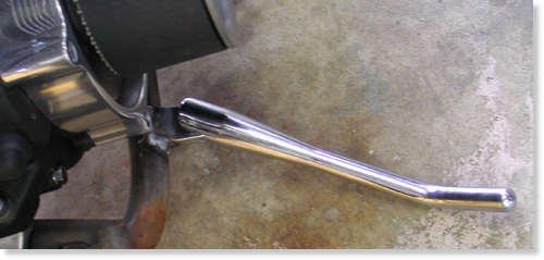
Bandit and I ordered everything from Joker point cover to forward controls that have zero slop, positive lever movement, built in stop light switch and adjustable foot pegs so you don’t vibrate off the pegs. They make all the difference in the world as Bandit attested to on his ride to Sturgis on the Blue Flame. We will doll up the Rev Tech black and chrome 88-inch engine with Joker Rockers that are fully machined from solid billet. The Wedge design enables total serviceability while the motor is in the frame. Bottom section is completely o-ringed. Base is clearanced for larger diameter valve springs and feature a unique modular baffle system for excellent venting characteristics. We’re also using their hand controls because according to Bandit they’re perfect. Our order contained a myriad of the little item also, like small triangular rear turn signals, mirror, gas cap, oil breather, throttle housing, billet clamps and bullet head bolt covers.
Finally we jumped into my truck and headed back tothe ribbon of shimmering hot asphalt of the 210 Freeway. By the time we gotto the 605 Freeway, it was 5:00PM and the Freeways were all at a turgidstandstill, constipated with lumbering gas guzzling, smog spewing cars andtrucks. It was one of those many moments when we wished we had those tight FXRs splitting lanes toward the cool salt air of the coast.
Doctor John promises to have the frame finished for pick-up next week. We’ll report from his Anahiem, Ca location.
If you’re in the Southern California neighborhood, Joker Machine is sponsoring a show at the Grand Opening of the Route 66 Roadhouse and Tavern, June 22 at 1846 E. Huntington Drive, Duarte, California. Call (626) 357-4210 for more information on the shows and Pig Roast.
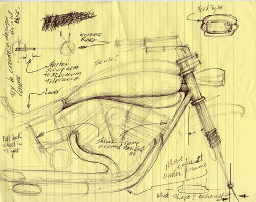
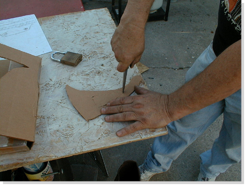
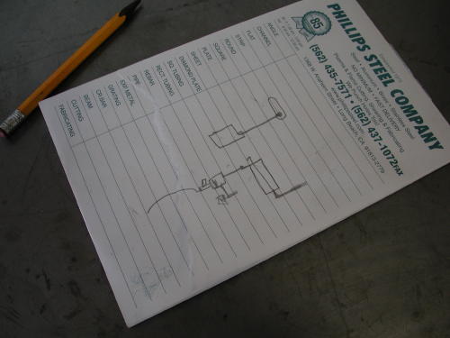
My first concept drawing which Bandit puked on and shit-canned.
Here’s the first of one of my bumbling concept sketches. We will be working with a racing Porsche sheetmetal fabricator on fenders, tanks and exhaust configurations. Wait until you see what Bandit and I come up with next.
Like the enigmatic fortunes you find inside thosefolded Chinese cookies, our visit with Dr. John–the”frame doctor,” was a mix of New Age mysticism andpractical guidance. The week before, Bandit and Ibrought the rolling Pro-Street frame to the gooddoctor. We gave the him our best ideas of what wethought the bike should become. Basically, we wantedthe bike to fit my body proportions, to shrink theframe around the engine and to still have elements ofa street chopper.
Bandit and I had been trying to create a bike that hada real “signature” identity, yet we weren’t sure whatthat would mean. We tried to convey our concepts withawkward babbling.
Stroking his long, gray beard with a knowing gravity,the doctor calmly listened to our ravings. Eventuallyhe gave us a broad grin through the tangle of beardand said, “Don’t worry, boys, I understand exactlywhat you need.”
We had left the bike with vague misgivings.”Do you think he really has a clue what we want?” Iasked Bandit.
“I dunno,” Bandit said, staring off into the acrid,smog-laden sky.”The guy’s kind of strange, but everyone I’ve talkedto says the guy’s a wizard,” Bandit musedmysteriously.
When we pulled up to Dr. John’s shop, there was ourcreation leaning up against the wall. Not averse tostreet-corner poetry, I intoned, “What a bitchin’fuckin’-lookin’ bike.”
“Man, that bike is really unique,” Bandit exclaimed ina more civilized tone.
As we oohed and ahhed about the bike, Dr. John camearound the corner, grinning. I jumped onto theseat-less bike and grinned. It fit perfectly, betterthan an O.J. leather glove.
“I really think you’ve got something good goingthere,” the doctor spoke with unconcealedappreciation. “I wasn’t sure it was going to workuntil I got into it. The bike began to speak to me. Ithink it’s got the right karma,” the doctor spoke withmysterious gravity.
All this mystery was not without reason. Dr. Johnstarted this trek to ultimate frame adjustment workingat Goodyear Tires. A fortuitous opportunity, sponsoredby Goodyear, for advanced training at L.A. Trade Techgave him the chance to try motorcycle repair.Recognizing that he was more interested in bikes thantires, he began a course in bike repair withinstructor Pat Owens.
Dr. John soon connected up with a bike shop calledMotorcycle Menders. Right away, he could tell that hehad a better-than-average sense of what was needed tofix most frames. Eventually, he opened his first shopin Covina in 1983. In 1990, he moved to his presentlocation in Anaheim.
Dr. John’s expertise is extended to both traditionalstreet choppers and to the more exotic road racebikes, where competitive tolerances and alignmentshave seconds off of lap times. The challenges to hisexpertise in frame adjustment include the extremes ofcreating a bike for a 6’9″ rider and a Harley with a25″ over stock front end. For his own use, he isbuilding a karma-tingling three-wheeler with a VWengine.
In his shop, amongst a tangle of tweaked Ninjacarcasses, “destruction derby” ATV frames, twistedchopper forks and even a mangled Vespa body, Dr. Johnholds court. Side-tracking his stories about gettinginto the frame adjustment business, he mixes conceptsof metal stresses with ideas of mental stresses,Eastern philosophy, acupuncture points, shakras andauras, martial arts movements, elements of a good dietand muscle alignment of the spine.
The conversation stumbles easily into his personalexperiences. After an injury of his own, he explored avariety of methods of pain control, eventually meetingan American Indian psychic whose exotic beautyhypnotized him as much as her cosmic consciousness.Here, a glint comes to his eyes and a wry smile bringsone corner of his mouth up. “A rare beauty,” hemuses. “An aura just like Cleopatra of ancient Egypt.”
Bandit nodded in agreement repeatedly, like thoseDodger dolls that bobble in the back windows of cars,to the good doctor’s banter. Bandit slurped his greentea while listening to enchanting tales spun by theDoctor. While I shoveled in heaps of steaming andspicy-hot Kung Pao chicken, my eyes teared up and mynose started running.
“The magnetic flow is a flux of energy in the bodyof…” The steaming pots of green tea and plates ofexotic Chinese food sent wisps and tendrils dancing inthe air above our table like a chorus of swaying,sensual nymphets.
“The assorted colors of shakra balance…” Thisadventure had the aura of Zeke the Splooty about it.We were on a cosmic motorcycle Magical Mystery tour.
An hour or so later, Bandit and I were back on the 91Freeway with the bike strapped to the bed of hispickup, staring ahead kind of dumbly. “What a trip,Dr. John is,” I said.
“Yeah, but I think he did a great job on the frame,”Bandit said.
“Yeah, cosmic man,” my head was stuck in the ’60s.”What do we do now?” I asked.
“Let’s check out some trippy paint for the bike,”Bandit smiled. “Let’s drive down to Stanton and see ifWes at Venom can come up with something exotic enoughfor this mystery machine.”
“Go for it,” I laughed.
It’s days like these that make bike building seem likethe right thing to do. Bandit slapped in a tape of’60s funk and we were sailing down the road like acouple of latter-day Kerouac and Keseys.

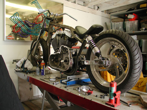
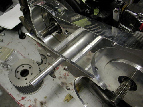
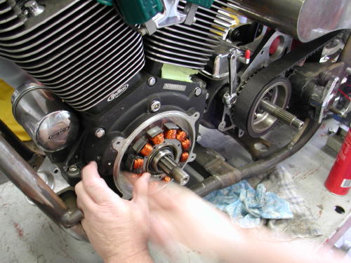
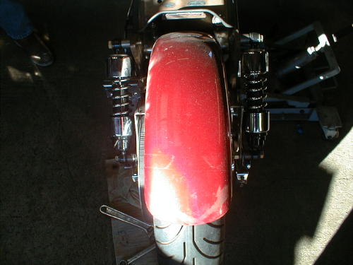
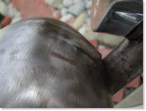
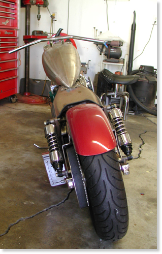
“Hand me a bigger hammer, goddamn it,” Bandit hollered across the garage. We were slamming together as much steel as we could to get this Frankenstein of a bike together in time to show it to the crowds at the Queen Mary Motorcycle Show this weekend.So far this week we’ve managed to cut 1.5 inches off the swing arm. This brings the wheel into the back end of the bike at the point of the pivot. We are designing the bike with brevity in mind. We are hoping that the finished impression will be a bike shrunken around the RevTech 88-inch motor and Rev Tech 6-speed. Oh, we’ll have devilish accents here and there, but the overall concept is lean and mean.
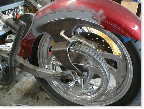
To that end, we are cutting off any unnecessary tabs and struts. Of course, everything changes as soon as a UPS box arrives. Joker Machine parts arrive every couple of days. The foot controls arrived. The new front Avon tire should be here Monday or Tuesday. It arrived, we had it mounted pronto and the fender was looking good. I hauled it to Urs who is a master body man and he widened it to fit perfectly. Having the right tools makes a big damn difference.
A new front tire was called for because the sexy front fender from Cyril Huze was too narrow, since he builds bikes for 19 and 21-inch from wheels and we’re running an 18 (our fault).
After banging the hell out of the fender to try to squeeze out a fraction of an inch clearance, we decided on a smaller sized tire. We ordered an 18/ 100-90. We hope this will allow us at least 3/8-inch all around.
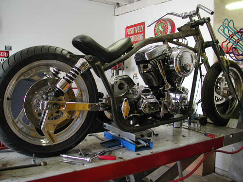
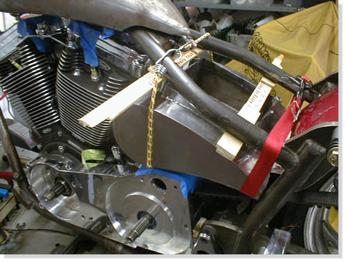
The new Cyril designed stretched tank arrived with the fenders. We cut out part of the bottom of the tank at the back where the front of the seat is, since every goddamn thing we do is backwards. Every builder in the country stretches bikes, we shrink ’em, so the tank won’t fit without mods. This move helped bring the tank down closer to the engine and since the FXR is short, well you get the picture. The tank tabs are in place and welded.
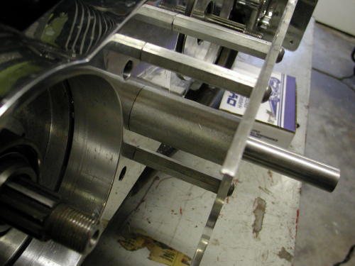
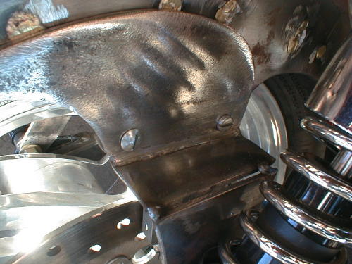
We decided to use an old rear fender off one of Bandit’s past bikes–a Fatboy. We turned it around backwards, the front end will be bolted to the center of the swing arm. Our next problem was how we were going to hold up the stern. After a lot of head scratching, cussing and phone calls we met with master fabricator James Famighetti who suggested that we create our own struts that will be bolted on the inside of the lower rear shock absorber bolt, then welded to the outside of the fender in such a way as to add to the over all look and strength of the fender and conceal the stock aspects. Mounting fenders to swingarms is treacherous. It will vibrate like a dog attacked by killer bees, so it better be strong and still able to remove for touchup.
No problem, you say? Ah, ha, not so easy kimosabe! We are pretty sure the strut will have enough clearance for the Rev-Tech brakes on the right side of the rear tire. When you come around to the left side, you’ve got the pully to contend with. So on this strut we added a 2″ dog leg to clear the pulley. I made up the patterns on cardboard and the Fam-Art brothers cut and bent the pieces. Then it was time to fit. We’re getting there.

The BDL pulley from CCI is smaller than the one we used for the mock up. So with our fingers crossed, when all these parts come together this week it will be amazing if they all fit. They did, well, perhaps not perfectly, but we’re getting close.They did, well, perhaps not perfectly, but we’re getting close. If not, “Bandit, get me a bigger hammer, goddamn it!”
Here’s the score. The fender needs tabs and it’s ready. The rear fender needs rivet removal and the massive tabs tack welded. The shock tabs have been cut since the Progressive Suspension shocks from Custom Chrome need to be set wider away from the fender tabs. Let’s see if we can make it to the show. We’re still waiting on Huze oil tank mounting tabs.

The saga of the Amazing Shrunken FXR continues. This project is notonethat is merely slapping together after-market products to build a facsimileof a customized Harley-Davidson.From the start, Bandit and I sought to create a unique ‘signature’ bike.Even though we have used a lot of after-market products, most have beenmodified to fit our design plan. The products we use, from the FXRPro-Street frame to the Rev-Tech engine to the Joker Machine qualitycomponents, to Cyril Huze, Avon and BDLare some of the finest products available.

Because some of the fundamental elements of design were modified, we havebeen constantly fabricating new brackets, tabs, mounts, and studs. Eachmodification created new issues relating to the fit and function of thedrivetrain. It seems as if we’ve bolted and unbolted the elements of this bike ahundred times.For example, the frame was modified by Dr. John to fit the Rev-Tech engineinto our overall design concept. The top motor mount was bent to fit thenewspacing. We used this motor mount point to position the Cyril Huze teardropgas tank. When we positioned the tank we related it to the handle barclearance at maximum turn position. Rubber mount brackets were welded inplace. The tank was cut at the underside back end to fit low on the frame.It looked hot. Next I cut the La Pere seat pan to hug the pointed rear ofthe gas tank and strengthened the seat back. There is a continuousdouble-‘swoop’from the handle bars to the back of the rear fender. The seat pan lookedhot.
Then we tried to put the engine in. It didn’t look fit. The engine wasmere fractions of an inch from fitting. Even if we could have hammered itinplace the subsequent tight tolerances would surely create problems as thebike rattled and roared down the road.
At this point, we cut the original tank brackets and repositioned themodified tank a little higher on the top frame tubing. The tank looked hot,the engine fit, but now the handle bar swing is a fraction of an inch tooclose to the tank. This means we will probably have to have custom handlebars.
It still looks good and we’re still optimistic. Even as wedroppedthe tank down on the new rubber mount brackets and began putting in the5/16″bolts, we found that the right rear bolt was too long to fit. So we got abolt with a thinner head and with my small fingers, I got the bolt in andstarted. We were still looking hot.
We decided to see if the belt fit since Bandit had cut andrewelded the swingarm 1.5 inches shorter for that Amazing Shrunkenlook. Bandit said no, the belt wouldn’t fit. It wasn’t suppose to. Isaid it looked close. As welooked at the bike we realized we’d had to remove the engine, drop thetransmission, which meant we’d have to support the swing arm. It alwaysseems harder than hell to make something easy. So with a couple of scissorsjacks, hunks of wood, and a crow bar, we were able to loosen the rubbermounton the left side of the pivot point of the swing arm. Then we gingerlyslipped the belt in, put the rubber mount back and bolted everything backtogether. Damn! It fit perfect and we were looking hot.
Wait a minute. The right side of the belt was almost touching the edgeofthe back fender. Quick surgery with a saws-all cut a chunk out of thefender. Fender fits, belt don’t rub, bike still looks hot.
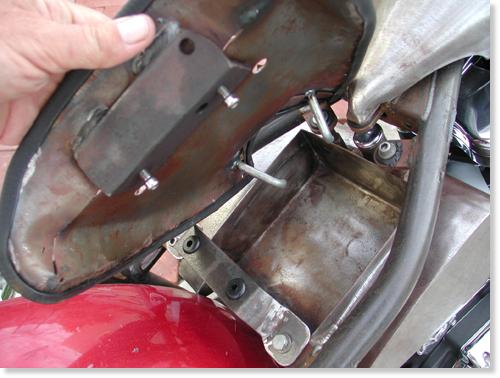
As we cram more operational parts together, the room to move gets lessandless. Next we positioned the oil bag, which also brought up the issue ofthebattery accessibility. With bungee cords, a busted yard stick and some woodshims, we finally got the bag in what seemed a reasonable position. Fourrubber mounted brackets were fabricated then welded into place. It lookedHot. Everything was bolted in place. And everything looked Hot.
Ah, but not so fast kimosabe. We shaved the fins off the back ofthe oil bag for more clearance. With the two rubbermounts in place atthe rear of the oil bag under the seat pan we had enough clearancefor the battery, in the front for the engine and exhaust, under itfor the starter motor, but no clearance for the ever moving rearfender. It needed at least 1.5 inches of shock play since it’sattached to the swingarm. We had to peel the bag out of the frame andtake it to the Famighetti’s metal fab shop, Fam-Art, for theirexpertise. They came up with a plan to scoop out the back of the bagto the battery box without shortening the overall look of the bag.Then the fender will have the clearance to move with the swingarm andstill look hot.
Next, we neet to investigate whether the Joker controls canbe mounted mid frame. At the same time we will begin fabrication ofthe Amazing exhaust system. It’s gotta be lookin’ hot one way oranother.

Bandit and I were checking out the Amazing Shrunken FXR. “Thedamned thing,” referring to the shrunken FXR project we had beenhammering at, off and on, for almost two years, “has attitude,” hegrowled, “a bad-assed attitude.”
“Yeah, but will it have sound attitude?” I mused. “I want it toget attention. I want it to be felt in their chests before they seeit. I want them to hide their children from the evil they fear.”
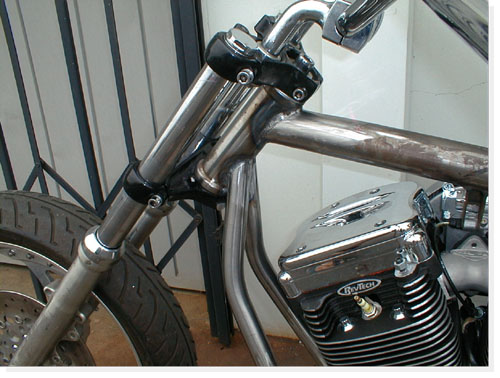
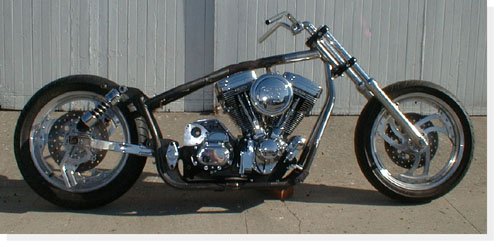
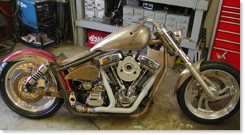
The Amazing Shrunken FXR has developed into a mythic ethos. Froma cardboard box full of rejected, beat-up, and cast off parts, thebike has become a sculptured icon, a physical dream, and perhaps awrong turn down a bad dirt road, three miles back.The project began back in the spring of 2001. After a lot of fitsand starts, the Buell Project, the Sturgis Run, the Deer Gut stewadventure, Bandit’s painful recovery, the Red Ball prep, variousevents including a trip around the world and soiree’s, we slappedparts on, hammered steel into shape, welded this and that, cussed andfarted and got to where we are with the help of a RevTech driveline,Custom Chrome, BDL belt, Joker controls, Cyril Huze sheet metal andCompu-Fire electrics. The bike is raw boned, trimmed down, and meanlooking. That’s where it stands, inert and waiting for inspiration,up on the rack at the Bikernet garage.
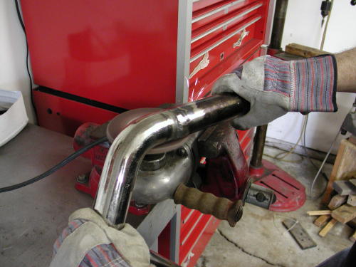
Bandit regarded the raw metal frame with squinty-eyed intensity.”What you thinkin’,” I asked, keeping my own gaze focused on thepotential of the bike. At my question he stretched out his gangly,egret-like frame to its full 6’5″. “It’ll be a loud mother fuckereither way you play it,” he intoned in his gravitas basso-profundodeep voice. “We’ve shortened the frame and rear wheel base so muchthat it’s barely a cunt-hair from the exhaust port to the rear wheel.”
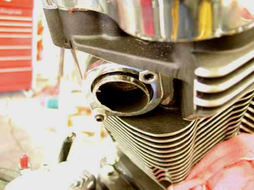
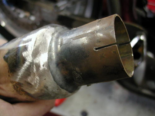
We cut a piece of an Samson Evolution system with a Mikita touse the exhaust port, then started welding other pieces in place. Wecut it back to make a tight turn and create space away from the oiltank.
“Fuck it,” I responded in my best Pancho Sanchezimprovisation, “let’s just start from the port and see what happens.”
We rummaged through a pile of Samson scrap exhaust pipes that wehad scavenged from a dumpster behind the Sampson factory. Flingingout fish tail tips, shot gun systems and swoopy cruiser exhausts,most of them dented and damaged so they couldn’t be re-used. Mr.Samson gave us only the best to modify. We eventually came up withenough pieces to fabricate a Frankenstein exhaust system.
As I grabbed for a section 1 3/4-inch chrome pipe, Imistakenly grabbed a goodly chunk of fur. Bandit’s midget, crazeddemon of a feral cat yeowled in protest and sank his needle-liketeeth into the back of my hand.
“God damn that crazy bastard,” I screamed, “he’s as crazyas a peach orchard boar.” I’m sure Bandit has a mescaline salt-lickfor that freaked out feline.After I extricated my hand from the jaws of Bandit’s feline Cujo, Ireturned to the exhaust system at hand.
Our intent was to minimize the exhaust system as much as possible.We ran the pipe straight down from the front exhaust port, thenturned it to hug the bottom of the engine case. We had originallyhoped to put a flattened pipe under the frame, but reasonable roadclearance dictated a different path. So we tucked it in and aroundthe engine case, then inside the frame, coming out just at the edgeof the back wheel.
“Our first mistake,” Bandit spouted, “we needed a smallerdiameter chunk of exhaust to form guides when welding chunks ofexhaust together. If we had slipped it in one piece even a quarter ofan inch. it would have held each chunk in alignment. That’s onetheory to building pipes. The key to fabing your own pipes is havingenough scrap to slice and dice, then cutting and working each pieceuntil it’s as close to a perfect fit as possible. Finally the tackingprocess is critical. That’s were the guides didn’t come in. If we hadguides we wouldn’t have offset pipes tacked into place. That problememerged severely a week later during the grinding process.”
“It took two days of playing, cutting, fitting and welding toform a completely custom exhaust system in place,” Bandit added.”Make sure you wet towels and form a fire barrior around your tackingarea to protect the rest of the bike. I used a small 0-sized torchtip and common hanger to tack the segments of pipes together. I’m notconfident enough with our new MIG welder with thin sheet metal, so Istuck with the torch.”

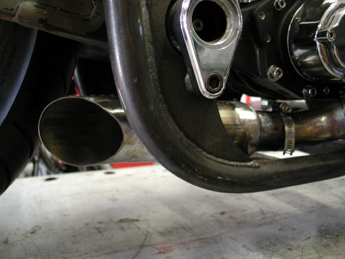
” It wasn’t perfect, but it was ours,” Bandit added, “acompletely unique system that would be tucked under the transmissionand attached to the driveline solidly under the tranny backing place.Then we faced the muffler aspect. The pipes were too short to be openor we would have been arrested within a block of the headquarters.”
Needing some kind of ‘standardized’ muffler elements, we went toour local San Pedro Kragen Auto Parts store. With the clamp-on piecein hand, we found parts and pieces enough to create a 7″ mufflercase. “Most of the elements were too heavy and glass packed,” Banditspouted, “We couldn’t weld on a glass pack.”
Back at the garage, with torch in hand, Bandit cut out a sectionof baffles from some scrap Sampson muffler. Spot welding the bafflesinto our jury-rigged muffler, we produced something that may, likeJapanese Fart Wax, diminish the painful ‘Brap-rap-rap’ flutter ofunrestrained exhaust back pressure. A right-angle turn-out willdirect the dragon’s breath exhaust from the screaming 88cc Rev Tech,high-performance engine to an unsuspecting public standingslack-jawed and terrified at the curbed edge of civilization, theirhair-dos blasted straight by the sizzling after-burner of the AmazingShrunken FXR.
“He gets sorta twisted,” Bandit muttered shaking his head.”Actually with the baffle in hand we went to San Pedro Muffler Shopand looked at the myriad of tips and tubing alterations we couldmake. We found a tip and had a chunk of 1 7/8 tubing spread to matchthe tip. That formed the other end of the muffler. We just had toweld the three elements together.”
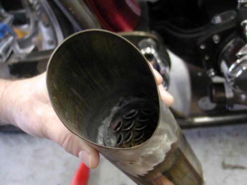
I welded the baffle in place, positioned as it was in theSamson System. I discovered that the two elements didn’t want to weldtogether. I have a feeling the tip was made of an inferior metal.
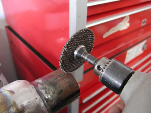
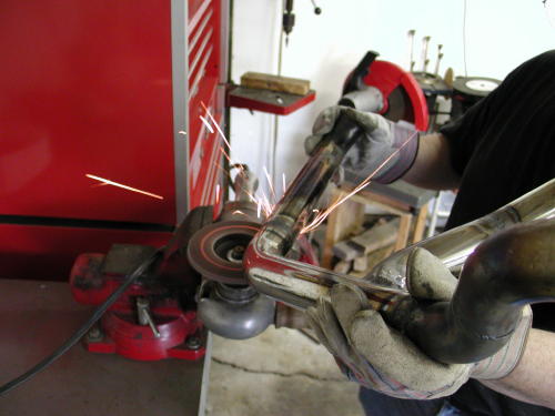
With the die grinder we cut notches for the muffler clamp.
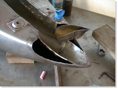
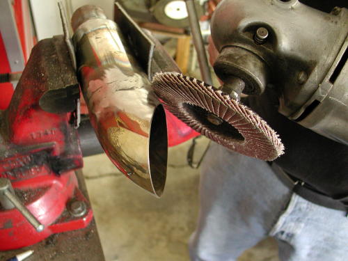
“After welding and fitting I stood back and was proud of ouruniquely tight system that would allow Giggie, from Compu-Fire, tomachine mid-controls for a final touch,” Bandit interupted. Theexhaust played perfectly into the Shrunken aspects of the project. Iremoved the tacked system and began hours of gas welding to make itwhole. That’s when all hell broke loose. While working on anotheraspect of the bike with my back turned to my partner, he began togrind the welds. The college art history professor sought perfectionwith each weld and ground right through the thin walls of the18-guage exhaust pipes. It was amazing. I was sure the system wasruined.”
This shows the amount of area ground down so far we were forcedto fill it or destroy the system and start over.
“Some builders tack systems together then take them tomuffler shops for professional construction. I thought that was mynext move. Unfortunately a regular muffler shop doesn’t have themandrels to make the tight bends we had proposed. I was devastated,but the man told me that he could fill the welds with his MIG welder.
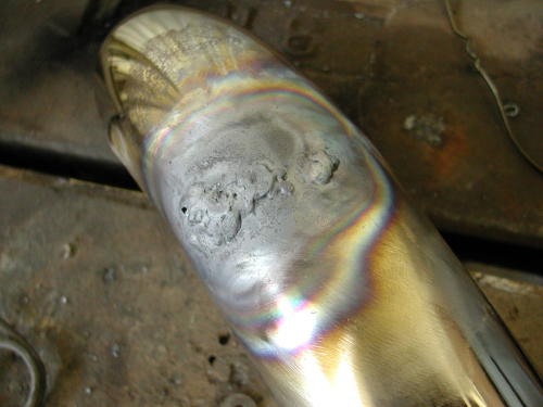
More welds to fill the mad grinder’s cutting work.
“Unfortunately each weld was now a 1/2 inch tall and wide zit atalmost each junction of the pipe. Nuttboy began the grinding processagain. More holes were found and I filled them with gas welding usinghanger rods. I joke now that if the bike runs like shit we blame iton the exhaust system. If it runs well, it’s the same roll of thedice. We’ll see.”
“Making your own exhaust system can be a blast, just don’tget heavey handed with the grinders. Pipe is thin and a little weldthat shows won’t matter much since we didn’t plan on chrome, butblack Jet Hot coating. I’ve sworn off chrome exhaust systems on mybikes for the future.”

That big bastard just won’t shut up. The next episode in thismechanical adventure will feature Giggy’s attempt a electrifying thesteel monster. Next weekend, barring any new bike projects, Giggy’sinopportune finger damage at the power tools, splattered deer guts,San Pedro political insurrection, Sin Wu’s beguiling charms, a caseof beer, or any other form of diversion or chaos, we will be closerto cranking this monster over.

Photos by Bandit and Sin Wu
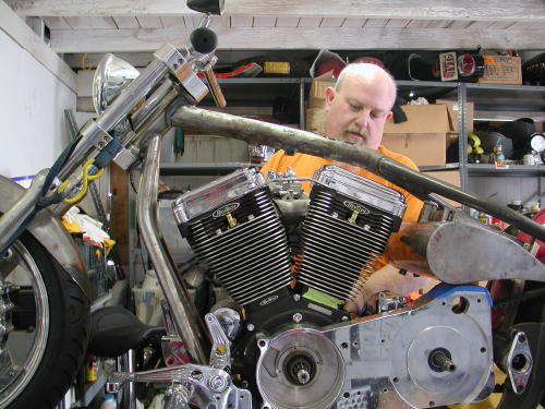
It’s New Years Eve 2002 and catch up time on the ShrunkenFXR, as if I’ll melt if I don’t cross the line by midnight. And I’mgoing to lower the boom on you. It wasn’t intentional that Giggie,from Compu-Fire, came to the Bikernet Headquarters to help install aCompu-Fire charging, starter and ignition system. He added showing usthe benefits of installing S&S solids in the 88-inch Rev Tech engine.That would seemingly be enough, but since the starter involved theBDL inner primary, Giggie was snagged into helping with the beltdrive installation. That’s not all. As you will see in some of theshots we have Joker Machine forward controls installed, but we’vealways considered mid-controls. Unfortunately for the mastermachinist, we asked for Giggie’s impression and knowledgeablenotions. He dove right in and you’ll see the outcome here. There’seven more, but let’s get started.
I’ve been running Compu-Fire Electronics for several yearsand will continue to do so. The systems are flawless and a breeze toinstall. I’ve learned to trust their components and enjoy asingle-fire ignition. My discussions with Giggie ran into startingproblems I had encountered before. He pointed out to me that newhydralic systems bleed down as engines cool which closes valves whenyou want that puppy to fire to life once more. That’s where the S&Sportion of this tech began.
Here’s the deal. If the valves are closed while the starter motoris desperately trying to turn over the engine, especially aperformance unit, it’s a bitch. The compression is over the top, andthe electric motor is fighting an up-hill battle. The battery isbeing stressed. This situation is caused when the bike sits and thehydraulic lifters bleed down. Once it fires to life that situation isrelieved.
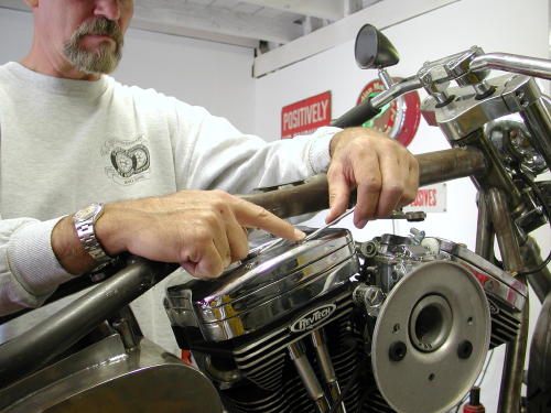
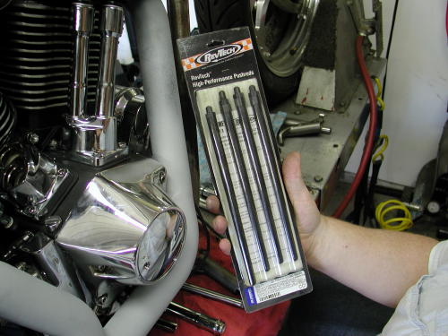
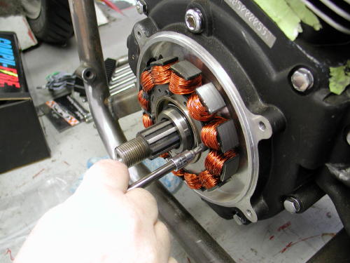
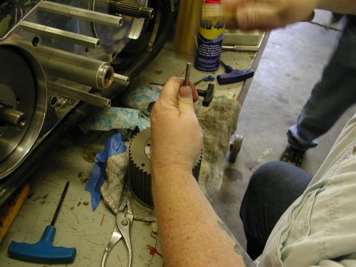
Giggie has been testing and improving starter systems for thelast three years with Compu-Fire. They are developing the mostelectrically efficient systems on the market, but discovered thishitch in the driveline system with the jammed valve train which putsundo pressure on an otherwise fine starter motor and battery. We madea date to install the new Compu-Fire Starter, but in addition, fourlittle rings from S&S would slip into the Rev Tech hydraulics. Sincethis Custom Chrome engine had non-adjustable pushrods we had to ordera set of Rev Tech aluminum adjustable pushrods. We removed the rockercover and arm assemblies to free the pushrods.
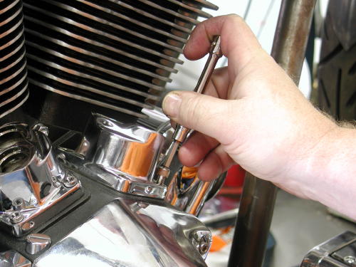
The lifter blocks had to be removed to retrieve the hydraulicslifters.
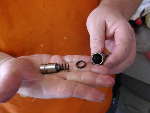
The following shots show the S&S solid ring installationprocess, I hope.
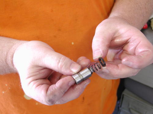
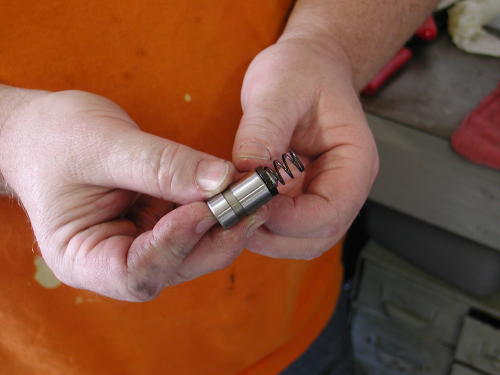
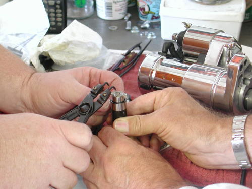
Giggie used snap ring pliers to remove and install the snapring to free the hydraulic piston.
With the lifter blocks removed, the lifter slipped outeasily, and with a snap ring plier tool Giggie removed the ring andthe spring and the piston came free. The S&S ring was slipped overthe hydraulic plunger spring and the rest is history. With the clipring back in place the hydraulics were ready to rock with the new RevTech Pushrods.
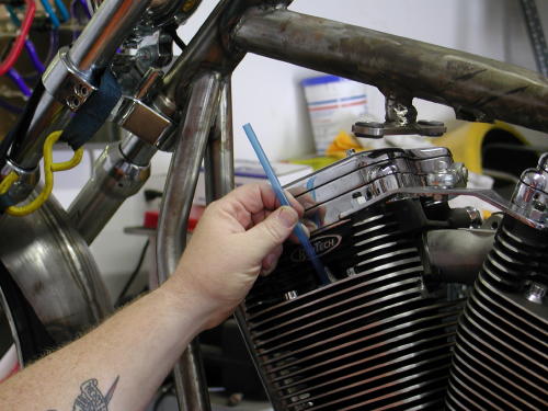
Giggie demonstrated how he adjusts pushrods by finding the intaketop dead center, TDC, position for the front cylinder first. When theintake valve is closing or the pushrod heading down, stick a straw orpencil in the spark plug hole and watch it travel north until it’s atthe top, TDC. check the timing hole for confirmation. Sure enough averticle slot showed up in the hole confirming our position. The camwas also in the perfect position to adjust both the intake andexhaust pushrods for the front cylinder, since both valves are closedfor compression. There is also an exhaust TDC.
The pushrods are adjusted just like old school, solids untilthere’s no up and down slack. You’ll notice that the rings don’t makethe hydralics completely solid but give them .020 slack. Once youhave each pushrod adjusted back off one complete turn. That will giveyou .020 cushion and once the bike runs for the first time you won’thave any tapping like the old scoots had. That’s an easy fix for amajor performance issue. I hate wasting starters or batteries.
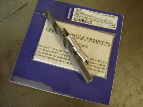
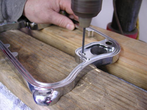
Since we didn’t have the adjustable pushrods on hand we tookthe rocker boxes apart and Giggie pointed out another big inch motorfix. Performance engines that are pushed to redline can build upexcessive oil in the rocker box breathers. That oil will end up inthe air cleaner if it doesn’t have time to filter back through theheads into the oil return line. Creative Cycle Products, distributedby Custom Chrome, designed a fix for this problem. They call this theNose Bleed Cure which was designed to work on all late 1993 and upEvolutions with Nose Breather (engine vents in the heads) system.Installed, the kit eliminates the collection of oil at the bottom ofthe air cleaner assembly. It allows the engine to breath naturallywithout the mess in the air cleaner. The vent extensions, installedin the rocker boxes, allow more time for the oil to filter throughthe head.
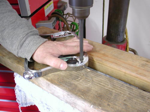
The vent extension is a breeze to install, especially if therocker boxes are removed. The center rocker arm spacer has two areasin the corners for breathers. The inside cavity has a rubbermushroom, Umbrella Valve, poised to limit some air and oil into thearea. That’s the corner we’re concerned with. The extensions wereeasy to install in some respects in the Rev Tech Rocker Boxes andcreated another challenge in other respects. Let’s follow CreativeCycle’s instructions: If we had a battery we would have disconnectedit, first. Since our tank was easy to remove we 86’d it to make roomfor the operation. You could get away with just jacking up the tank.
Remove the front rocker box top plate following the servicemanual. Unbolt the sucker. Then remove the center spacer. Remove thegasket. If the engine is new you don’t need to replace it. Theinstructions also call for replacing the Umbrella valve, but youdon’t need to do that unless it is old and worn or you bury it inaluminum shavings. Umbrella valves generally last a long time, butheat sometimes damages them and they crack. If you are going toinstall the cure in a worn performance engine, replace the UmbrellaValves.
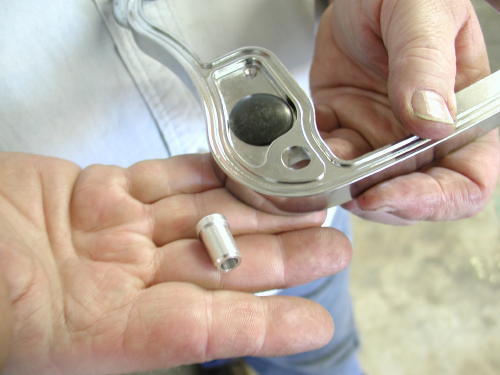
Drill the small drain hole with the supplied 1/8 bit. Using the13/32 drill, bore out the large drain hole. The Rev Tech rocker boxspacer already had a sizeable hole and didn’t need drilling. The ventextension slipped right in. On the opposite side of the spacer thehole was broad and open which didn’t secure the new vent extension atall, which is generally a mild press fit. We cleaned the spacerthoroughly and cemented the extension in place with sillicon on theunderside and let it set up before we re-installed the rocker with afresh gasket (generally the use of silicon on the inside of anyengine is forbidden. But since it’s Nuttboy’s bike, who cares). Makesure the ring is completely clean of any debri or burrs. In mostcases, according to the instructions, the vent extention is a pressfit into the new hole. Tape it gently into place, clean the rockerring thoroughly and re-install that bastard.
Now perform the same function with the rear head. Accordingto the diagram with the kit, the two breather sections you’re lookingfor are the inboard units closest to the carb. Makes sense. Theoutboard breather cavities are not used. If you are running a monsterengine and want to extend the extension, there are small ringsincluded in the kit to enhance the existing extension although youmay need to clearance the top rocker box cover.
One more time I’ll mention silicone. It’s not to be used in anengine since one little piece could severely block an oil passage anddestroy the engine. The other reason I mentioned it again was broughtto bear by Frank Kaisler and a neatly placed .38 against my righttemple. He whispered angrily in my ear that silicon will not cementitself to chrome. He suggested JB Weld after the chrome was groundaway for a clean sticky porous surface.
That’s two out of say five techs we need to cover. How thehell are we doing? If you have any questions about this modification,here’s the number for Creative (800) 368- 6217.

This entire tech process was handled in two differentsessions. During the first we discussed the mid controls notion withGiggie and he altered our course. We were headed in the direction ofstock FXR mid control mounts, that bolt or are welded to the frame.That notion would force us to created large sweeping mounts to clearthe BDL belt drive. Giggie had another notion. Run a shaft throughbushings built into the belt drive inner and outter covers, tolinkage much like stock through primaries, except we would mount thefoot peg on the end of the shaft for the cleanest possible approach.
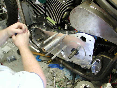
On the right side of the bike we had to make a plate that wrappedaround the tranny cover that would carry a similar shaft that wouldact as the axle for the brake lever. He suggested that we hide themaster cylinder under the tranny close to the rear wheel for a tighthose run to the rear brake caliper. The pipes will wrap around theshaft for the right peg and brake lever. Seemed like a good idea,except for one thought. This is a rubber mount motorcycle and boltingthe pegs to the driveline was asking for foot vibration. We discussedthe concept with several riders and the reactions were varied from”we’re nuts”, to “What the hell”, to the notion that we could run oneset of billet pegs for around town and a vibro-padded set for theroad. We decided to run with Giggie’s concept and try the simplesuckers out.

When we met with Giggie again he demonstrated the outcome.He machined the shaft for the BDL unit and an aluminum guide tubewith brass bushings pressed into the covers. The support unit wasstrong enough to stand on. Next, we needed linkage and a shifter peg,then foot pegs. In this case the foot peg will rotate with theshifter, another odd approach.
Note the high-dollar precision sketch of right rear brakelinkage mechanism. I don’t get it, do you?
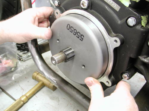
Moving right along we installed the Compu-Fire chargingsystem. This is a breeze, but first you must hit the Harley Shop oryour Custom Chrome Catalog for a set of Stator Torx screws. If you’renot sure which charging system you have here’s a clue: The 32-ampalternator kit is identified by the stator plug protuding from theleft crank case outer surface. The 22-amp stator plug is recessedinto the crank case surface. This particular system is designed tofit all Big Twin models 1981 and later. The rotor may be used withstators rated at 22 amp and 32 amps.
We used the contact cleaner for clearing the stator area ofgrease or debris. The WD-40 was used to let the plug slip into placegently.
We cleaned the area in the left side of the Rev Tech casesthoroughly with contact cleaner. Then we slipped the stator over themain shaft, but not into position. Giggie sprayed the alternator plugwith WD-40 and began to wedge it into the inner slot in the case.First you need to back out the Allen set screw in the case to allowthe plug to slide through. Once the plug is in position (protruding1/4 inch), tighten the Allen set screw with Permatex blue Loctite. Becareful not to over-tighten the screw which could short out thealternator and ruin your day. With the plug in place make sure thewires are safely routed then install and tighten down the stator withthe self Loctite’d Torx screws. Done deal.
Then Giggie slipped the smaller of the two massive washersover the shaft (except when 32 amp Harley-Davidson alternator kit isalready installed). If the Compu-Fire rotor is being installed on a1981-1988 model with the Harley-Davidson 32-amp alternator kitalready installed, the spacers and shim washers should already beproperly positioned on the sprocket shaft. Discard the washerssupplied in the kit and reuse the washers and shims in the samelocation from where they were removed. Compu-Fire charging systemsare perfect replacements for toasted charging systems.
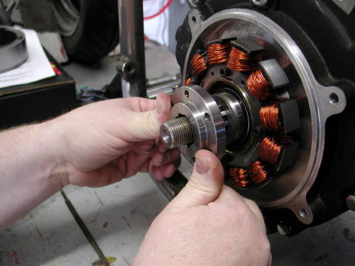
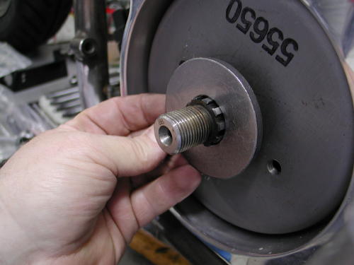
Then he took the BDL engine shaft insert and slipped it onto thesplined sprocket shaft to check the fit. Some sprocket shafts fromJIMS and S&S were slightly different sizes. The splines were machinedto be .001-inch larger across the face. Since the BDL insert fitsnugly, but fit he attempted the same manuever with the Compu-Firerotor. When we installed a rotor on the Redball chopper, we had tofile each tooth to make it fit. That wasn’t the case this time aroundsince Giggie ordered the Compu-Fire rotor with the larger slots orsplines. Note the number on the rotor. The 650 unit is alreadyprepared for the larger shaft, whereas the 600 unit was built forearlier alternator motors. If you need to remove an old rotor you mayneed a JIMS machine tool or a Harley-Davidson puller part no.95960-52B. Be careful that the magnets in the rotor do not pick upsmall metal parts or hardware from the work area before you installit.
Also note the warning label on the rotor. It says not tosmack the rotor with anything. If you do so severely you could knocka magnet loose, or you could change the polarities on the magnets.Don’t hit it with anything harder that the palms of your hand. Thisone was snug, but slid right into place. Now comes the large flatwasher. This puppy is there for strength. With everyday use the faceof the rotor will flex and can crack. This washer adds strength tothe face and prevents cracking. Don’t forget it.
Here’s some notes regarding different models. Thisinformation is supplied with all Compu-Fire charging systems:
To install rotor on 1981 to 1990 Big Twin) except those witha 32 Amp alternator kit installed) place the large washer suppliedand original shim washers over the sprocket shaft (in that order).See figure 1.
To install rotor on 1991 and later FLT/FXR models, discardthe large washer supplied in the kit. Place the original washer andshims over the sprocket shaft (in that order). See figure 2.
To install rotor on 1991 and later Softail and Dyna Glidemodels, discard the large washer supplied in the kit. Place theoriginal shim washer over the sprocket shaft. The original thickspacer washer will be used under the compensating sprocket nut onfinal assembly. See figure 3.
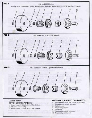
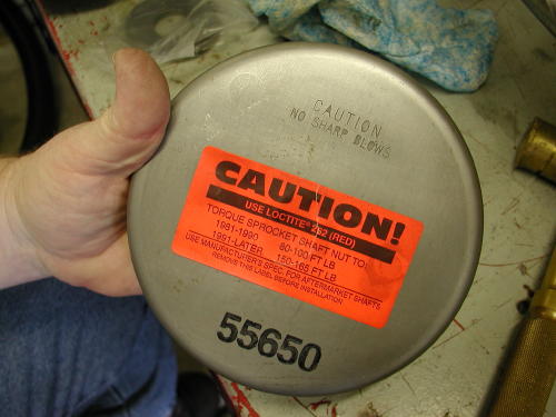
If your are installing this Compu-Fire kit on a stock bike,next you would re-install the primary drive assembly per factoryservice manual and use loctite (red) on the threads of compensatingsprocket nut. The compensating nut must be torqued to the correctspecifications:
1981-1990 models 80-100 foot pounds
1991-Later models 150-165- foot pounds
(for aftermarket shafts use manufacturers specifications.)
Don’t forget to put oil back in the primary.
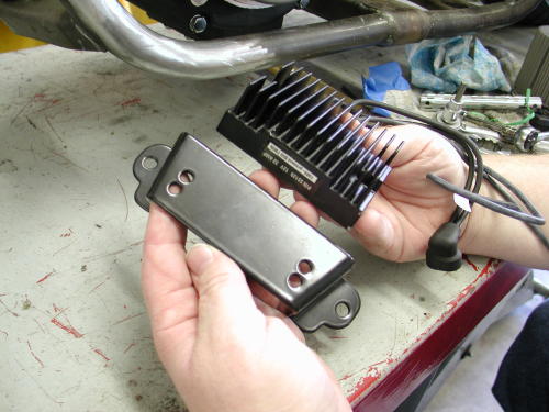
That left the regulator. In the past you would be forced toinsure a proper ground by cleaning some of the regulator case surfaceof paint, the bracket surface and paint off the frame. That’s nolonger the needed. These regulators come with a separate groundstrap, which Giggie recommends that you attach to the engine case onthe right side under the cam cover to hide it. “Make sure the wire iscrimped to a lug, not soldered,” Giggie pointed out, “and that thecase is clean of wrinkle paint before it’s bolted in place.”
One other wire is afforded with the regulator, the hot wire,which generally runs to a circuit breaker, the battery hot terminalor the ignition switch hot side. There’s a specific reason for notsoldering lugs or connectors, but crimping them. According to Giggiesoldering induces heat to the wires and a completely solid lead bondthat creeps under the wire insulation. The combination creates abrittle point in the wires that can deteriorate and crack withvibration. Wire connectors do not come with the regulator kit. Youneed to find the appropriate size for your application.
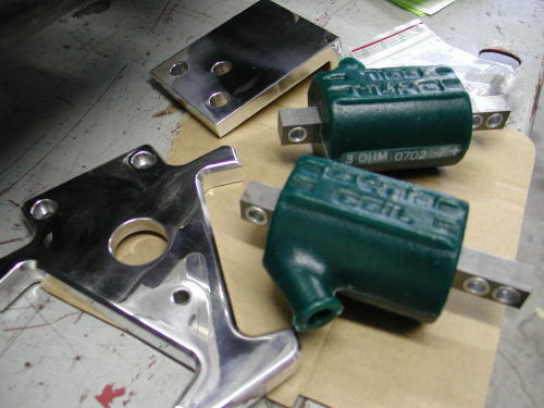
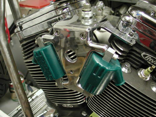
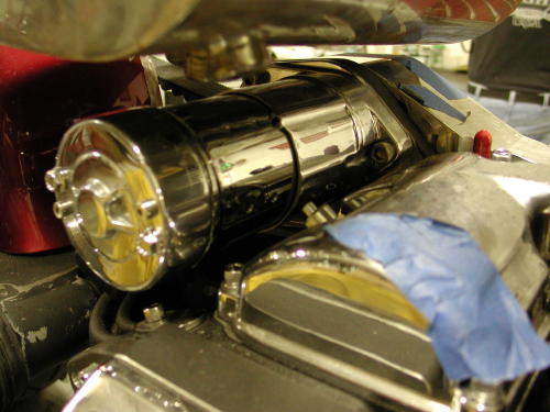
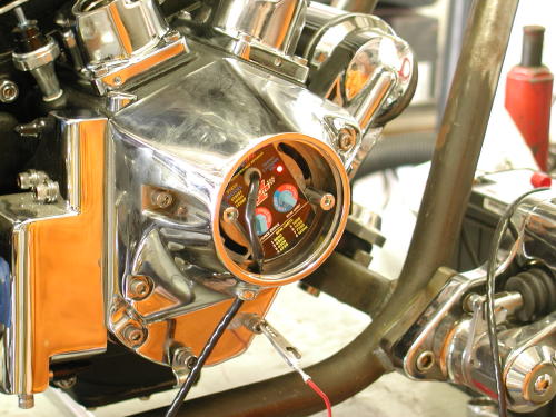
While Giggie was tinkering in the Compu-Fire machine shop,building prototype components for their line of products and slippingin a Shrunken FXR parts, in his free time, we installed 3 ohm Dynacoils required for the single-fire Compu-Fire ignition system. Theyare available from Custom Chrome in 6 and 12-volt models, with singleor dual towers and in 1.5, 3.0 and 5.0 ohm configurations. We chose astrong billet German made bracket, from Custom Chrome, to hold thecoils between the heads. This is one of the cleanest ways to run theelectrics with all the elements close together. The coil bracket fromCustom Chrome was also capable of holding the ignition switch and ahorn button or toggle high/low beam switch. That would be the extentof the wiring for this bike and it would all be tucked under the gastank and between the heads cleanly.
We have also ordered a CCI ignition switch discovered from thewater-craft industry by Bob McKay. It works like automotive ignitionswitch with a key and acts as the starter button eliminating the needfor a starter relay.
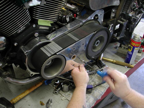
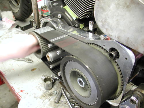
What should we handle next, the ignition system or the BDLBelt Drive? Your call? The BDL Belt, okay, here goes. Actually theseunits are increasingly easy to install. Late model bikes with rubbermounted drive lines are in solid alignment which makes these unitslip right into place. Just in case you are working with a pre-unitmodel I will list some alignment recommendations from Frank Kaisler.
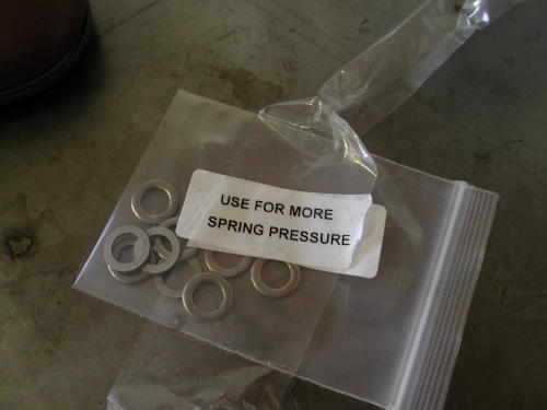
This particular BDL installation came with their brand new SuperStreet Clutch which consists of nine fibers and 11 steels. Installtwo steels first then alternate fiber and steel ending with a steelbehind the pressure plate. Install anywhere from four to nine springsand bolts depending on how much spring pressure is needed for yourapplication.
“With this much clutch surface, not much spring pressure will beneeded for proper engagement,” Said Bob from BDL. For additionalspring pressure for monster engine and abusive clutch throwers theyincluded washers to enhance the clutch pressure.
Basically Giggie installed the backing plate first using thefasteners supplied by BDL. Installation on 1986-89 models require theuse of a 1990-up starter and modification to the starter mountinghole on transmission will be necessary. You must open the mountinghole to 2-1/8 inches.
Remove the stock starter pinion gear and complete starter gearassembly from starter. Bolt starter into back side of motor plate.
Install the front and rear pulleys and check for proper fit. Atthis time you should determine if the front pulley will need shimmingor not depending on how the pulleys align with each other. Removepulleys and add shims if necessary.
Re-install belt drive placing front pulley, rear pulley and belton at the same time or you’ll discover it’s tough going. Install andtighten to H-D specifications, mainshaft hub nut. BDL supplied aspecial hub nut with seal for all spline shaft models 1990 and later.Engine shaft splines should not protrude from the pulley. Be sure tored Permatex Loctite front engine nut and torque to H-Dspecifications (an electric impact driver is used but notrecommended). JIMS and CCI carry a tool that will lock the pulleys soyou can use a torque wrench. For 1986-89 taper shaft models you mustuse the stock hub nut and seal kit (included).
For spline mainshaft models, 1990-up, apply red Permatex Loctiteonto the back of the BDL hub 1/4-inch inside of the spline and letthe Loctite flow onto the mainshaft when sliding the rear basketassembly on. This procedure is necessary so that the hub andmainshaft will fit together properly and will not let the mainshaftspin inside of the BDL hub. This procedure is not necessary on tapershaft models 1986-89.
(The belt drive was designed with the use of stock H-D frames.The shaft to shaft dimensions on a stock Softail are 12.825 and on anFXR is is 11.325. The number of teeth on the pulleys and the numberof teeth on the belt were engineered to exact fit using the abovedimensions. If aftermarket frames, engines or transmissions are usedthen these dimensions may very slightly. You may need to address thisproblem so that the kit will fit properly. We will not be able tohelp you with this problem, this is an issue to be addressed by themanufacturer of the aftermarket parts that you may be using.)
Rotate the motor (take the plugs out) using a socket wrench, thebelt should track straight and away from the motor plate, but not sothat it may come in contact with the outside pulley flanges. Be surethat the belt drive is not making contact with the motor plate.
Grease the starter shaft and install the BDL starter pinion gearonto the starter shaft, apply red Permatex Loctite to the starterbolt and tighten to H-D specifications (they supply two starter boltswith the kit, one is a 1/4-20 by 2.5 inches for 1990-93 starters, theother is a 10-32 by 2.5 inch for 1994 and up starters. Be sure not totighten starter bolts too tight as this may interfere with properengagement to the clutch ring gear.)
Install the clutch pack, refer to schematic spline steel first,1/2 sided friction plate with fiber facing out, then alternate steeland two sided fiber plates ending with the other 1/2 sided frictionplate with the fiber facing in. This is for the regular clutch andnot the Super Street Clutch which was covered above. Install pressureplate, springs and shoulder blots.To install shoulder bolts apply redPermatex Loctite to a bolt and run in one turn, go onto the next boltuntil all the bolts are in place, then tighten them all the way downuntil they bottom out. There is no adjustment to the spring pressure,this is all pre-determined with the length of the shoulder bolt andexact dimensions of our pressure plate.
Install the four hexagon cover plate extensions into motor plateand mount side guard with the four button head allen blots.

Clutch screw adjustment should be 3/4 to 1 turn loose from lightlyseated. Note: When the clutch is hot the adjustment screw should notbe seated. Tighten rod nut when adjustment is complete. BDL suppliesa clutch adjusting rod and nut for all models 1990 and up, only.
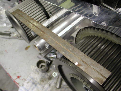
If your bike is perfectly level, if you put a level on thisruler, it should be level.
SIDEBAR; ALIGNMENT CHECKS FOR RIGID MOUNT DRIVE LINESWith the engine in place and all the lower engine mounting boltsinstalled but loose, take a straight edge and place it on the innerprimary mounting surface of the engine. Look at the straight edge toinsure that the sprocket is parallel to the straight edge, if not trymoving the engine around until the straight edge and sprocket areparallel.
Once this is done snug the rear engine mounting bolts. Now checkthe engines front mounts to the frame with a feeler gauge, if thereis a gap between the engine and frame make some shims to fill thegap. The shims should be a plug fit. A plug fit is the same as a slipfit, the exact shim height to fill the space between engine and frame.
Position the transmission on the trans plate and install in theframe. Place all plate mounting hardware in their respective holes,but leave them loose.
Place the BDL engine plate on the engine and the transmission andinstall all of the mounting hardware. Tighten the plate to enginemounting bolts first, then the plate to transmission bolts. Usingyour hand turn the mainshaft of the transmission to feel forresistance, this is how you will check your work.
This shows the primary before installing the pulley and the masterCompu-Fire designer/machinist Giggie.
As of right now, you have assured the engine’s sprocket shaft andthe transmission main shaft are parallel to each other. Now tightenthe transmission mounting plate to the bottom of the transmissioncase. Check that all of the trans plate mounting bolts still movefreely up and down, if they or only one of them don’t move freelyfind out why and fix before moving on. Sometimes this occurs due tomanufacturing tolerances. Sometimes just running a 3/8-inch drill bitthrough the frame and mounting plate will fix small misalignments.
Here is where the difference is made. It is a lot easier to shimthe transmission mounting plate to the frame mounts than thetransmission to the mounting plate. To do this take a set of feelergauges and measure the gap at each trans plate mounting bolt, thenmake-up a shim to “plug-fit” the distance. With all four corners ofthe trans plate done check the “fifth” trans mount and shim as needed.
The moment of truth. Start tightening the transmission mountingplate bolts one at a time. Check the transmission main shaft byturning it in your hand before and after tightening each bolt. If youfeel increased resistance after a bolt is tightened then you willneed to go back and check that you got the correct shim thickness forthat one mounting bolt. Keep checking the mainshaft and proceed tothe rest of the mounting bolts. After all the mounting bolts aretight and the mainshaft spins as it should, you’re done.
A good way to double check your work is once everything is tight,remove the engine plate. The engine plate should not pop or springwhen the mounting bolts are removed, and likewise the plate should goright back on and seat against the engine and trans with no effort.
Ok, where to get shim stock. There are a number of machine toolcatalogs that sell a selection of shim stock for about $20-$30. Theseselections come with different thickness sheets of stock that you cutto whatever shape you need. Another source of shims is PerformanceMachine and Custom Chrome. Both companies sell brake calipers thatsometimes need to be shimmed to their mounts to center the caliperover the disc rotor. The mounting bolts for these calipers are3/8-inch diameter, the same size as your transmission mounting platehardware, I have bought a couple packs of these shims to use. If Iremember right they were only a few bucks per pack. If for somereason you have a big gap between the plate and frame you may be ableto use a 3/8-inch flat washer. Most flat washers these days measureout between .060-.068-inch in thickness, you may still have to addanother shim to achieve the plug fit you are looking for. Anothersource of shim stock is beer or coke cans, if I remember correctlythese cans measure out at around .014-inch, but it has been a longtime since I measured one.
The main thing to remember, is that the mainshaft must always turn free,maintaining its parallel course with the engines sprocket shaft.
When speaking of parallel shafts, that’s plural parallels.Both planes, vertical and horizontal. Believe it or not, careful set-up ofthe belt drive, or chain drive frees-up hidden horsepower.
When both shafts turn parallel, true parallel, requires the least amount ofpower to turn. Freeing that extra few ponies to do your bidding, not tomention better fuel mileage.
–Frank Kaisler
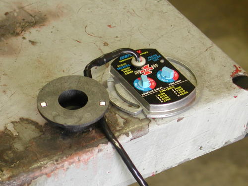
Compu-Fire Ignition model 21835 installation–the last hurtle.For kickstart you need the 21835KS. The electric-start unit delaysspark for two revolution to allow the starter to get rolling.
We are finally to the bottom line, the last straw, the final beerin the six-pack. We face only the simple, yet precise Compu-Fireignition system. I’ll try to make it quick.
First find front cylinder top dead center TDC as we describedbefore with the straw (won’t hurt anything) in the sparkplug hole,after the intake valve begins to close. The notch on the cam shaftwill be at 7:00 at TDC and you know that you’re cool. There shouldalso be a straight verticle line in the timing hole, anotherconfirmation.
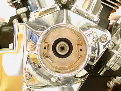
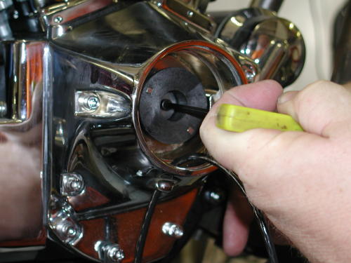
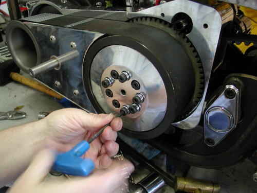
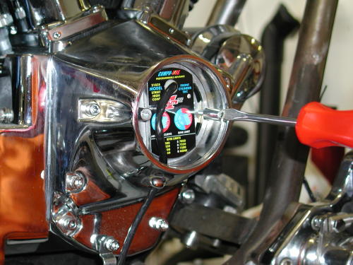
First you need to remove any previous ignition systemright down to the cam shaft. Now bolt in the Compu-Fire ignitionrotor or trigger wheel with some blue Loctite. Giggie then bolted inthe Compu-Fire ignition plate and turned in counter clockwise. Afteryou run the wire loom out the bottom of the Rev Tech cone. Dig out a12-volt battery and hook the red wire to the positive terminal.
Tape off the black, white and green wires so they don’t ground orshort to the battery. Power the red wire up with a ground link to thebike. The LED light on the Compu-Fire plate will alight.
Grab the magnet that comes with the kit and hold it with theHarley orange dot away from the plate and swipe the magnet left toright along the bottom of the plate. The light should go out, if not,turn the magnet over and try again. Slowly turn the plate clockwiseuntil the exact moment the light goes on again. You’re timed, donedeal, simple. You’ve static timed the bike in its advanced position.Lock the plate down and disconnect the battery.
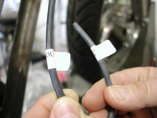
You wire this with with the red wire heading to heignition switch. It’s the hot wire. The Black wired hauls ass to thefront coil, the white wire to the rear coil and the green to the VOESswitch. That’s the single-fire set up. For Dual fire aim the blackwire to the coil and tape off the white wire. The green is guided tothe VOES advance switch once more. Giggie likes the VOES switch andI’ll try to explain why. I would prefer to throw it in the trash, butnooo. We will install the VOES switch in the wiring tech, later.
I like the concept of single fire for a smoother running engineand separate coils for each cylinder for a stronger spark. Some maysay, “Bullshit.” But that’s my notion of single-fire ignitions. Thisunit has two switches, let’s start with the left. You turn it to dualor single-fire and it has eight advance curves. One to three are setfor 35 degrees BTDC advance. Four to six are 32 degrees of totaltiming, seven is 30 degrees and eight is 28. There are threedifferent curves bringing the engine to total advance at differentRPMs, one is 1,500, 2 at 2,000 and three at 2,500, based on themotor. We set it at six because I’ll be running the VOES.
The right switch controls the VOES. You can have it set at50 percent or 100 percent. Fifty percent is advanced 5 degrees and100 percent, 10 degrees. It adds timing at necessary times but willnever add timing over the advanced maximum. The final setting on theright is the Rev Limiter. The best use of the rev limiter is to setit 500 rpms past peak power. That means some testing is needed to useit effectively. No problem. It’s designed to prevent over revving themotor because of a missed shift. The right hand switch controls theVOES and the rev limiter.That’s it goddamnit. I can’t believe I made it to the end. Wejust hauled the Amazing Shrunken FXR to our master metal fabricator,James Famaghetti for final craftsmanship. We need to install aSportster kickstand kit from Custom Chrome and Giggie’s controls,then it’s the three “P”s, paint, powder and plating and this puppywill rock. Hang on. We’ll be back in a couple of weeks.–Bandit
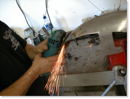
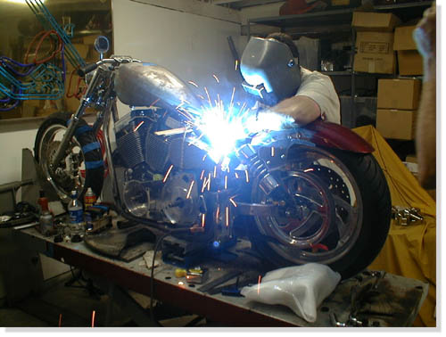
You’ve been there. You handed the Makita cordless drill toyou’re drunken buddy, and he drilled a hole in your big screentelevision. You tried to wrap the extension cord around his neck andfinish him off. We came close to blows in the garage a couple ofmonths back. I spent days carefully welding chunks of Samson exhaustpipes together to form a one-of-a-kind exhaust system.
All the welds were performed with gas and hanger rod. Thepipes weren’t perfect, but they fit the bill. They were actuallyintended to be prototypes, to be duplicated by a paid professional.After the first pass was completed the pipes fit like a glove,although they were artistically rough around the edges. Nuttboy cameby on his Wednesday afternoon escape, and I handed him a highspeedgrinder and instructed him to round off the welds. I worked onanother project and paid no attention while sparks flew. When he wasfinished he tapped me on the shoulder and said humbly, “Not sure thisis what you had in mind.”
He had ground right through the pipes and left gapingholes alongside most of the welds. In addition, I discovered to myteeth-grinding dismay, that there were still large sections of thepipe ground so thin, that as soon as the torch tip came within 6inches of the surface the pipe melted away. I spent another whole dayfilling the gaps. Who knows what will happen when the struggling bikefires to life. We’ll have the only exhaust system on earth withbaffles throughout.
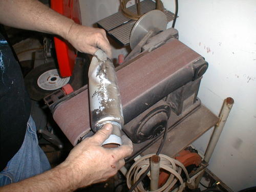
That’s not all. The grief continued. I hand made a mufflerusing a portion of a Samson baffle. We purchased a chromed, truckfender tip from San Pedro Muffler and went to work, but after hoursof screwing with the shiny metal we almost shitcanned the unit. Thefender tip was made out of a strange metal, almost pot metal, thatdidn’t seem to take to the gas welding and wouldn’t respond tobrazing. For every hole I filled, another crack lurked. I welded,then smoothed on a bench grinder only to find cracks and holes tofill again. The shorty muffler probably weighs 50 pounds due to thevast layers of welding rod. As it stands, this is a pure prototypeexhaust system. We should use it for testing then shitcan the rankpiece of shit and start over.
Click to order Catalog!
Frustrated, but pleased with the overall look we were readyfor final metal work. This bike is being built by inexperiencedhands, not professionals, in our backyard garage. Sure, I’ve builtsome bikes, but I wouldn’t consider myself a metal fabricator. I cameup with the initial design and we roughed out elements, but we neededa master metal worker to finish what we started. There are preciousfew, true metal craftsman, who I know. One is Billy Westbrook,another is Jesse James and recently, in the news, we displayed metalwork by Roger at Goldammer (Goldammer Cycle Works Ltd.,www.goldammercycle.com ,1-250-764-8002). High quality workmanship.
They’re out there but not on every corner. I stumbledonto another super-slag artist under my nose. James and LarryFamighetti are Hamsters and own a corrugated steel metal shop inHarbor City, California, called Fam-Art. You’d be tweaked to rumbledown Narbonne Street and stumble across this rusting corner buildingthat’s got to be the oldest swaying dump on the block. Theyspecialize in structural steel (you could never tell it from theircreaking tin shed) for homes and buildings. Large chunks of steel,massive shredders, presses and welders are scattered around the funkylocation that’s reminiscent of the first shack Harleys were built in.

Nuttboy and I darkened their doors a couple of times toask them to flame-cut a couple of chunks of steel for our fenderbrackets. The more I hung around the more quiet-James began to showme steel components he had fashioned for some of the local riders. Herebuilt and reformed Harley taillights to eliminate all the edges andgrooves, then welded them to fenders so that ultimately there were noseams. The more I gawked at the sculptured parts, that demonstratedhis ability, the more I knew we had discovered a man capable of BillyWestbrook fabrication qualities. We hauled the entire FXR to Jamesthe next week.
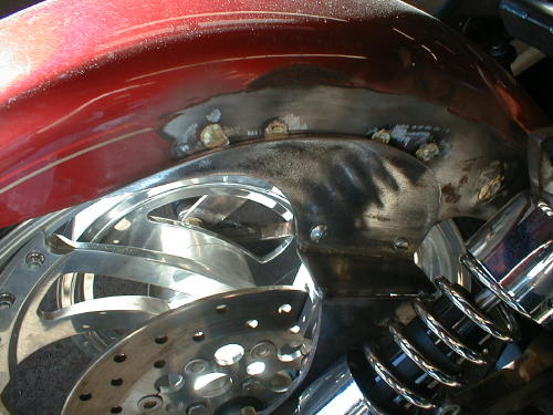
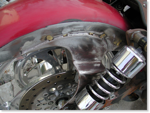
James relocated the straps in such a way to narrow the shockplacement keeping that shrunken look in mind.
This is a close-up of the right fender strap. It’s beencorrected, reformed and readied for final welds.

We cut and fitted the tank and made the mounts, butJames filled the underside, rear section for a perfect fit.
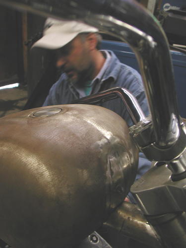
We jacked up the front of the tank and mounted it, butJames filled it and formed the front of the tank to match the customridge along the top. He even made paint work suggestions that I foundinteresting. “If you paint a ridge like this with a light color,”James said, “The ridge will disappear.”
We decided to paint the bike a light House of Kolors pearland create a dark teardrop panel on the top of the tank. He alsocreated and welded fork stops to the neck.
As we rolled out of the shop that day James still hadfinal welds to complete. He straightened out our seat pan, but neededto figure out a mounting arrangement. Finally we needed the CyrilHuze front fender brackets checked and welded into place.
We should have the Shrunken FXR back in our clutches inthe next couple of weeks. We need to finish our rear brake andshifting mechanisms with Giggie from Compu-Fire, fire it up for atest ride and tear it down for paint.
Oh, I need to untie Nuttboy. I need that extension cord.
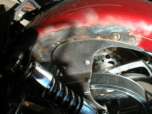
The Shrunken FXR returned recently from Fam Art, in HarborCity, California (310-326-2141). They welded, shaved, mounted theseat, manufactured fork stops and saved our poor- construction asses.James Famighetti mounted our Cyril Huze front fender, welded andformed the tabs and informed us that the Avon Venom was too large forthe narrow glide front end. It was our turn to work on it.
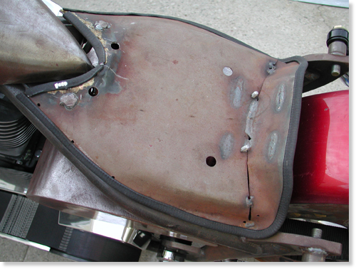
Note that James mounted the seat pan so that the edges wouldnot touch the frame paint in the future.
Like any self-respecting bikers we hate to have a bike, oreven components out of our mistrusting mitts. We had another dilemmathat needed handling. The bike still didn’t have a kick stand, and weused two 2 by 4’s, to hold it upright, when not perched on the lift.There’s a trick to this maneuver. If I backed the Pro Street FXR outof the garage and wasn’t hauling the wood planks, I was screwed. Ifalone, I could stand there for hours waiting for someone to strollpast carrying two 2 by 4s–unlikely. After a couple of unsteadyoccurrences, the bike didn’t move without the wood chips on the seat.You can imaging the major pain in the ass this caused.

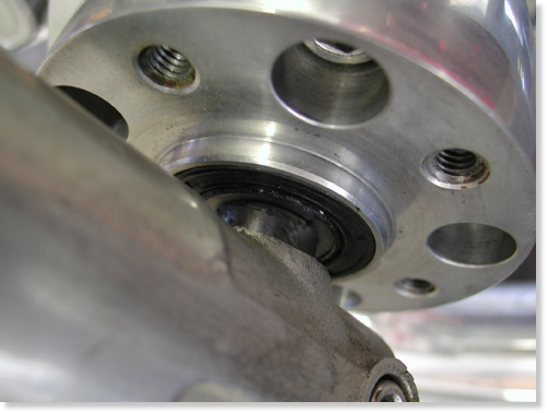
We ordered a weld-on, Sportster style, kick stand fromCCI, and it arrived complete, with all chromed hardware and thebracket to be welded on the frame. There was one problem indetermining the position. The front Avon was a 100/100 18-inch, andwe planned to replace it with a 90/90. We needed to have the finishedPerformance Machine wheel in place.
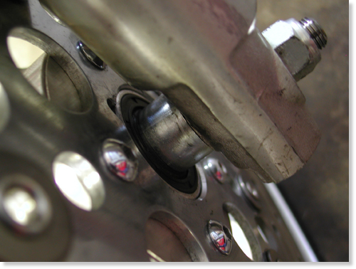
The Avon Road Runner tire arrived, and we had it installed at thelocal Yamaha dealer. James pointed out to us that our front tirespacing wasn’t perfect so I sliced a spacer to give us about a1/4-inch spacer on the right side of the wheel and about a 3/4 inchspacer on the left. The tire, almost centered, now had clearance, andthe wheel floated effortlessly under the modified Cyril Huze frontfender.
Now we were cleared to install the Hot Match weld-on kickstand.This is a tricky assembly process. First, you need to be absolutelysure you don’t plan to change the front wheel, to a 21, or extend thefront forks. If you do, the kickstand will need to be bent ormodified to fit. It’s not the end of the world, but it will destroythe chrome.
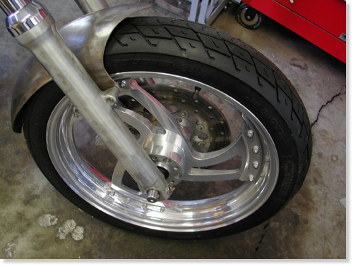
The other trick is determining the right position. Here’swhat my feeble brain told me, since the directions with the Hot Matchdidn’t cover positioning, except to recommend that you take yourtime–no shit. First I stood my Road King straight up and lifted theside stand until it was locked in place. Then I measured from thepoint that would touch the pavement to the ground. It varied fromaround 2.5 inches to 3 inches. I noted that the Hot Match lever wasnearly 3 inches shorter from the point of contact to the center ofthe pivot point. I took that into consideration. I also noted that Ihad lowered my King with shorter shocks, then added a larger Avontyre (a 150). Ground clearance was also a consideration.

Then we picked a placement area on the frame. Our designcalled for little or no forward controls. I kept the tab under theBDL belt drive system and hidden as much as possible, without beingso far back as to create a balance problem. If the weight is forwardof the kickstand, sometimes it can topple the bike. One otherconsideration. When the stand pops up you need to be able to reach itwith a toe, and it better not ride on the belt, or you’re toast. Makesure to check all that, before you burn any rod.
I sprayed the frame rail and the components with asilicone splatter preventative. It obstructs slag from sticking tocomponents. It also made the frame a slipper bitch. I tried settingthe stand end on a socket nearly 3 inches off the deck. Then Iconsidered the differing lengths of the stands and shifted to 2.5inches. Sin Wu was called, from the bedroom, to hold the stand firmlyin place. I marked it, with a grease pencil, then ground the edges ofthe bracket to be welded to the frame. Extra grinding took place toform a snug, metal to metal fit. In order to make all this work weneeded to partially assemble the kickstand without the ball andspring.
The easy-to-read directions called for disassembly, but we left ittogether and used it to hold the bracket in place for tacking. Beforetacking I backed the bike out of the clamp, holding it upright,positioned the bracket in the white grease pencil marks and leanedthe bike carefully until the stand rested on the flat surface. Itlooked cool, so we re-clamped the bike securely, held the stand inplace, protected the belt from hot slag and tacked the sucker withour Millermatic welder. Then we took the stand arm off the bracketand welded it some more. That would hold it securely until we torethe bike down for paint.
The Hot Match unit from Custom Chrome is a well madeprecision unit delivered show chromed. The instructions includedrecommendations to apply anti-seize to the spring and ball. Theyendorse using Red Loctite on the pivot pin threads. We didn’t becausethe bike would be torn down for paint in the near future. The armneeds to be placed firmly over the bracket and pushed into placebefore the pin will ease into the hole from the bottom. It doesn’thurt to have a spare set of hands and someone holding the bike.There’s also a pivot pin set screw to prevent losing that preciouspivot pin and kick stand arm, on a desert highway, in the middle ofArizona.
That’s it, except to mention that when we head to thepaint shop, we need to tape off the chrome bracket, so the painterwill paint over the welds but not the chrome tab.
As you can see this bike is damn close to the spray booth.I need to coerce Giggie, from Compu-fire, to ride his FXR out to theBikernet Headquarters with our mid-controls. Once the Joker Machinehandlebar controls are bolted to the modified bars, we’re ready for atrial run, then off to paint. Stay tuned.

–Bandit